D-Link 1250G Product Manual - Page 7
Unpacking, Installation, Rack Mounting, Connecting Network Cable - support
 |
UPC - 790069272462
View all D-Link 1250G manuals
Add to My Manuals
Save this manual to your list of manuals |
Page 7 highlights
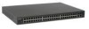
UNPACKING AND INSTALLATION This chapter provides unpacking and installation information for the Switch. Unpacking Open the shipping cartons of the Switch and carefully unpacks its contents. The carton should contain the following items: One Web Smart 48+2G-Port 10/100/1000Mbps/SFP Switch One AC power cord, suitable for your area's electrical power connections Four rubber feet to be used for shock cushioning Screws and two mounting brackets CD-Rom with Web Management Utility and User's Guide If any item is found missing or damaged, please contact your local reseller for replacement. Installation The site where you install the hub stack may greatly affect its performance. When installing, consider the following pointers: Install the Switch in a fairly cool and dry place. See Technical Specifications for the acceptable temperature and humidity operating ranges. Install the Switch in a site free from strong electromagnetic field generators (such as motors), vibration, dust, and direct exposure to sunlight. Leave at least 10cm (about 4 inches) of space at the front and rear of the hub for ventilation. Install the Switch on a sturdy, level surface that can support its weight, or in an EIA standard-size equipment rack. For information on rack installation, see the next section, titled Rack Mounting. When installing the Switch on a level surface, attach the rubber feet to the bottom of each device. The rubber feet cushion the hub and protect the hub case from scratching. Rack Mounting The Switch can be mounted in an EIA standard-size, 19-inch rack, which can be placed in a wiring closet with other equipment. Attach the mounting brackets at the Switch's front panel (one on each side), and secure them with the provided screws. Figure 1. Combine the Switch with the provided screws Then, use screws provided with the equipment rack to mount each Switch in the rack. Figure 2. Mount the Switch in the rack Connecting Network Cable The Switch supports 10Mbps Ethernet or 100Mbps Fast Ethernet and it runs both in half- and full- duplex mode using two pairs of Category 5 cables. The Switch also supports 2-Ports Gigabit Ethernet that runs in Auto-negotiation mode and 10Mbps Ethernet or 100Mbps Fast Ethernet that runs both in half- and full- duplex mode and 1000Mbps Gigabit Ethernet runs in full-duplex mode using four pairs of Category 5 Cables. These RJ-45 ports are Auto-MDI type port. The Switch can auto transform to MDI-II or MDI-X type, so you can just make an easy connection that without worrying if you are using a standard or crossover RJ45 cable. There are additional two mini-GBIC ports for optional mini-GBIC/SFP modules. 9
-
 1
1 -
 2
2 -
 3
3 -
 4
4 -
 5
5 -
 6
6 -
 7
7 -
 8
8 -
 9
9 -
 10
10 -
 11
11 -
 12
12 -
13
-
14
-
15
-
16
-
17
-
18
-
19
-
20
-
21
-
22
-
23
-
24
-
25
 |
 |
