D-Link 1250G Product Manual - Page 8
Identifying External Components
 |
UPC - 790069272462
View all D-Link 1250G manuals
Add to My Manuals
Save this manual to your list of manuals |
Page 8 highlights
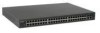
IDENTIFYING EXTERNAL COMPONENTS This chapter describes the front panel, rear panel, and LED indicators of the Switch. Front Panel The figure below shows the front panels of the Switch. LED Indicators Mini GBIC Ports 10/100 Base-TX Twisted-Pair Ports 1000 Base-T Twisted Pair Ports Figure 3. Front panel of 48+2G-port Gigabit Ethernet Switch LED Indicator: Comprehensive LED indicators display the status of the Switch and the network (see the LED Indicators chapter below). Fast Ethernet Ports (Port 1~48): These ports support network speeds of either 10Mbps or 100Mbps, and can operate in half- and full- duplex transfer modes. These ports also supports automatic MDI/MDIX crossover detection function gives true "plug and play" capability, just need to plug-in the network cable to the hub directly and don't care if the end node is NIC (Network Interface Card) or switch and hub. Gigabit Ethernet Ports (Port 49~50): The Switch is equipped with two Gigabit twisted pair ports, supported auto negotiable 10/100/1000Mbps and auto MDI/MDIX crossover detection function. These two ports can operate in half-duplex mode for 10/100Mbps and full-duplex mode for 10/100/1000Mbps. Note: When the port was set to "Forced Mode", the Auto MDI/MDIX will be disabled. mini-GBIC (SFP) Ports (Port 49~50): The Switch is equipped with two mini-GBIC ports, supported optional 1000BASE-SX/LX mini-GBIC transceivers. Port 49 and 50 are the same ports with the mini-GBIC no.49 and 50 ports, when the mini-GBIC transceiver is plugged in, the device will activate mini-GBIC, and the RJ-45 port will be disabled. Reset: The Reset button is to reset all settings back to factory defaults. Note: Be sure that you record the setting of your device, or else all settings will be erased when pressing the "Reset" button. Rear Panel Figure 4. Rear panel of the Switch AC Power Connector: This is a three-pronged connector that supports the power cord. Plug in the female connector of the provided power cord into this connector, and the male into a power outlet. Supported input voltages range from 100-240V AC at 50-60Hz. 13
-
 1
1 -
2
-
 3
3 -
 4
4 -
 5
5 -
 6
6 -
 7
7 -
 8
8 -
 9
9 -
 10
10 -
 11
11 -
 12
12 -
 13
13 -
14
-
15
-
16
-
17
-
18
-
19
-
20
-
21
-
22
-
23
-
24
-
25
 |
 |
