D-Link 3624I Product Manual - Page 14
Identifying External Components, Front Panel - des e
 |
UPC - 790069221859
View all D-Link 3624I manuals
Add to My Manuals
Save this manual to your list of manuals |
Page 14 highlights
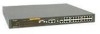
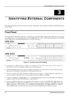
Stackable NWay Ethernet Switch User's Guide 3 3 IDENTIFYING EXTERNAL COMPONENTS This chapter describes the front panel, rear panel, side panels, optional plug-in modules, and LED indicators of the Switch Front Panel The front panel of the Switch consists of either 22 or 20 (10/100 Mbps) Ethernet/Fast Ethernet ports, two or one uplink jacks, a slide-in module slot for 10/100 Mbps Ethernet ports, an RS-232 communication port (DES3624i, DES-3624iF, and DES-3624iFM only), and LED indicators. Figure 3-1. Front panel view of the Switches ♦ Comprehensive LED indicators display the conditions of the Switch and status of the network. A description of these LED indicators follows (see LED Indicators). ♦ An RS-232 DCE console port is used to diagnose the Switch via a connection to a PC and Local Console Management (DES-3624i, DES-3624iF, and DES-3624iFM only). ♦ Twenty or twenty-two high performance NWay ports all operate at 10/100 Mbps for connection to servers and hubs. All ports can be auto-negotiated between 10Mbps or 100Mbps. ♦ A slide-in module slot (labeled Slot1) for 10/100 Mbps Ethernet ports can accommodate the following modules: 2-port TX, 2-port FX (MT-RJ), or 1-port FX (SC). ♦ One or two MDI-II uplink jacks are supported. Port numbers 1 and 2 on the DES-3624, DES-3624F, and DES-3624FM are equipped with MDI-X jacks for normal end-node connections and MDI-II jacks for uplink connections. Port number 1 on the DES-3624i, DES-3624iF, and DES-3624iFM are equipped with an MDI-X jack for normal end-node connection and an MDI-II jack for uplink connection. 18 Identifying External Components
-
 1
1 -
2
-
3
-
4
-
5
-
6
-
7
-
8
-
 9
9 -
 10
10 -
 11
11 -
 12
12 -
 13
13 -
 14
14 -
 15
15 -
 16
16 -
 17
17 -
 18
18 -
 19
19 -
20
-
21
-
22
-
23
-
24
-
25
-
26
-
27
-
28
-
29
-
30
-
31
-
32
-
33
-
34
-
35
-
36
-
37
-
38
-
39
-
40
-
41
-
42
-
43
-
44
-
45
-
46
-
47
-
48
-
49
-
50
-
51
-
52
-
53
-
54
-
55
-
56
-
57
-
58
-
59
-
60
-
61
-
62
-
63
-
64
-
65
-
66
-
67
-
68
-
69
-
70
-
71
-
72
-
73
-
74
-
75
-
76
-
77
-
78
-
79
-
80
-
81
-
82
-
83
-
84
-
85
-
86
-
87
-
88
-
89
-
90
-
91
-
92
-
93
-
94
-
95
-
96
-
97
-
98
-
99
-
100
-
101
-
102
-
103
-
104
-
105
-
106
-
107
-
108
-
109
-
110
-
111
-
112
-
113
-
114
-
115
-
116
-
117
-
118
-
119
-
120
-
121
-
122
-
123
-
124
-
125
-
126
-
127
-
128
-
129
-
130
-
131
-
132
-
133
-
134
-
135
-
136
-
137
-
138
-
139
-
140
-
141
-
142
-
143
-
144
-
145
-
146
-
147
-
148
-
149
-
150
-
151
-
152
-
153
-
154
-
155
-
156
-
157
-
158
-
159
-
160
-
161
-
162
-
163
-
164
-
165
-
166
-
167
-
168
-
169
-
170
-
171
-
172
-
173
-
174
-
175
 |
 |
