D-Link 3624I Product Manual - Page 16
Stack Operation
 |
UPC - 790069221859
View all D-Link 3624I manuals
Add to My Manuals
Save this manual to your list of manuals |
Page 16 highlights
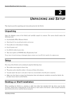
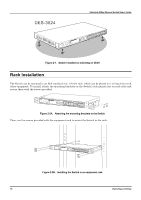
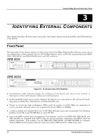
Stackable NWay Ethernet Switch User's Guide Figure 3-3. Side panel views of the Switch ♦ The system fans are used to dissipate heat. The sides of the system also provide heat vents to serve the same purpose. Do not block these openings, and leave adequate space at the rear and sides of the Switch for proper ventilation. Be reminded that without proper heat dissipation and air circulation, system components might overheat, which could lead to system failure. Stack Operation The DES-3624i, DES-3624iF, and DES-3624iFM are all intelligent Switches capable of acting as a master for up to three slave Switches (DES-3624, DES-3624F, or DES-3624FM). Each port is referred to by unit ID and port number in your DES-3624 Series stack. To set up a stack, a one-port Stacking input/output module is needed for each client Switch and a threeport Stacking input/output module is needed for the master Switch. Once the modules have been installed, use a cascade cable to connect each client Switch to the master Switch. Figure 3-4. Switch stack with one master and three slaves Please note that two client switches can also be connected via the Stacking input/output ports. The following diagram displays some possible switch stack connections: 20 Identifying External Components
-
 1
1 -
2
-
3
-
4
-
5
-
6
-
7
-
8
-
9
-
10
-
 11
11 -
 12
12 -
 13
13 -
 14
14 -
 15
15 -
 16
16 -
 17
17 -
 18
18 -
 19
19 -
 20
20 -
 21
21 -
22
-
23
-
24
-
25
-
26
-
27
-
28
-
29
-
30
-
31
-
32
-
33
-
34
-
35
-
36
-
37
-
38
-
39
-
40
-
41
-
42
-
43
-
44
-
45
-
46
-
47
-
48
-
49
-
50
-
51
-
52
-
53
-
54
-
55
-
56
-
57
-
58
-
59
-
60
-
61
-
62
-
63
-
64
-
65
-
66
-
67
-
68
-
69
-
70
-
71
-
72
-
73
-
74
-
75
-
76
-
77
-
78
-
79
-
80
-
81
-
82
-
83
-
84
-
85
-
86
-
87
-
88
-
89
-
90
-
91
-
92
-
93
-
94
-
95
-
96
-
97
-
98
-
99
-
100
-
101
-
102
-
103
-
104
-
105
-
106
-
107
-
108
-
109
-
110
-
111
-
112
-
113
-
114
-
115
-
116
-
117
-
118
-
119
-
120
-
121
-
122
-
123
-
124
-
125
-
126
-
127
-
128
-
129
-
130
-
131
-
132
-
133
-
134
-
135
-
136
-
137
-
138
-
139
-
140
-
141
-
142
-
143
-
144
-
145
-
146
-
147
-
148
-
149
-
150
-
151
-
152
-
153
-
154
-
155
-
156
-
157
-
158
-
159
-
160
-
161
-
162
-
163
-
164
-
165
-
166
-
167
-
168
-
169
-
170
-
171
-
172
-
173
-
174
-
175
 |
 |
