D-Link ANT24-1400 Installation Guide - Page 22
ANT24-0800, ANT24-0801, ANT24-1200, ANT24-1201, ANT24-1400 - cable
 |
UPC - 790069239939
View all D-Link ANT24-1400 manuals
Add to My Manuals
Save this manual to your list of manuals |
Page 22 highlights
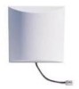
Indoor/ Outdoor Antenna Table: Model Name Signal directivity Application range Gain (Without cable loss) Approximate Range at 1 Mbps * Approximate Range at 11 Mbps * Half power Beam width ** Pigtail cable length Antenna fixed connector Surge protector for outdoors Default Extension Cable Length Default mounting configuration Antenna-kit weight (kg) Optional accessories ANT24-0800 Omni-directional Outdoor 8dBi 2Km 600M H360 V15 NA N-jack Included 50cm Pole 1.4Kg Ultra low loss cable For ANT24-CB series ANT24-0801 Directional Outdoor 8.5dBi 2Km ANT24-1200 Directional Indoor only 12dBi 3.5Km ANT24-1201 Directional Outdoor 12dBi 3.5Km ANT24-1400 Directional Outdoor 14dBi 5Km 600M H70 V65 30cm N-jack Included 3M Wall/ pole 1.04Kg Ultra low loss cable For ANT24-CB series 1.6Km 1.6Km 2.5Km H80 V23 NA SMA jack --3M Window/ wall 530g Ultra low loss cable For ANT24-CB series H50 V50 30cm N-jack Included 50cm Wall/ pole 380g Ultra low loss cable For ANT24-CB series H30 V30 30cm N-jack Included 50cm Wall/ pole 2.35Kg Ultra low loss cable For ANT24-CB series *1.Extended range reference based on RF-Output Power 14dbm with default cable loss *2.The transmission distance range might depend on the two same spec antennas with default cable loss **HPBW: Half Power Beam Width. H : horizontal plane pattern, V : vertical plane pattern The actual Indoor range will be effected by users' physical environment. The above figures are reference.
-
 1
1 -
2
-
3
-
4
-
5
-
6
-
7
-
8
-
9
-
10
-
11
-
12
-
13
-
14
-
15
-
16
-
 17
17 -
 18
18 -
 19
19 -
 20
20 -
 21
21 -
 22
22 -
 23
23
 |
 |
