D-Link DBG-2000 Quick Install Guide - Page 3
Installing and Connecting the, Device
 |
View all D-Link DBG-2000 manuals
Add to My Manuals
Save this manual to your list of manuals |
Page 3 highlights
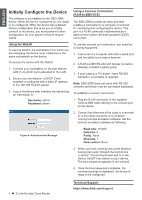
ENGLISH DBG-2000 Default Interface Settings Ethernet Interface LAN(1-4) / WLAN WAN Interface Type Static IP DHCP Client IP Address 192.168.10.1 Web-Based Management Enabled DHCP Client Enabled 0.0.0.0 Disabled Disabled Table 3: Default Interface Settings Note: DBG-2000 allows Web GUI access from LAN and Wireless interfaces by default for security reason. Installing and Connecting the Device This chapter describes how to connect cables and power to the device. Before You Begin Observe the following precautions to help prevent shutdowns, equipment failures and injuries: - Before installation, always check that the power supply is disconnected - Ensure that the room in which you operate the device has adequate air circulation and that the room temperature does Not exceed 40˚C (104˚F) - Allow 1 meter (3 feet) of clear space to the front and back of the device. - Do not place the device in an equipment rack frame that blocks the air vents on the sides of the chassis. Ensure that enclosed racks have fans and louvered sides. - Correct these hazardous conditions before any installation: moist or wet floors, leaks, ungrounded or frayed power cables, or missing safety grounds. Connecting Power and Turn the Device On/Off back panel of the device. Note: We recommend using a surge protector for the power connection. To power on the DBG-2000 device, press the DC power switch on the rear panel to the on position. To power off the device, press the power switch to the off position. Connecting the Device to a Network This section provides basic information about physically connecting the DBG-2000 to a network. To connect the necessary cables as shown in Figure 3. 1. Connect an RJ-45 cable from the port labeled WAN to the external router. The port WAN is pre-allocated to the WAN network segment. 2. Connect an RJ-45 cable from the port labeled LAN (1-8) to a switch in the LAN network segment. 3. Connect an RJ45-to-DB9 cable from the console port for CLI (Command Line Interface) management access. Internet WAN Switch LAN Console User Figure 3. Basic Cabling Example The AC/DC Power Adapter shipped with the device connects the device to earth ground when plugged an AC grounding-type power outlet. The device must be connected to earth ground during normal operation. To connect power to the device, plug the AC/DC power adapter into the DC power phone jet on the D-Link Nuclias Cloud Router 3
-
 1
1 -
 2
2 -
 3
3 -
 4
4 -
 5
5
 |
 |
