D-Link DCS-3411 Product Manual - Page 6
Hardware Overview
 |
View all D-Link DCS-3411 manuals
Add to My Manuals
Save this manual to your list of manuals |
Page 6 highlights
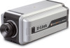
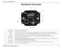
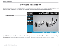
Section 1 - Product Overview Hardware Overview 2 3 1 4 5 11 6 7 10 98 1 Power Receptor Connects to the supplied power adapter. 2 DI/DO Wiring I/O connectors for external devices. 3 Power LED The power LED is on the back of the camera. As soon as the power adapter is connected to the camera, the LED will turn green. 4 Iris Level Used only when the DC-Iris lens is connected. When adjusting the Iris level, you can determine the brightness of the video images. 5 Link LED A solid green light indicates a connection to an Ethernet device. The light will blink during data transmission. 6 Reset Button Reset will be initiated when the reset button is pressed once and held until the Power LED flashes through its cycle twice. 7 Microphone Port Use to connect an external microphone. 8 BNC Connector The BNC connector is used for professional video connections. It benefits users who integrate digital IP camera into traditional system (CCTV) for both analog and digital video streaming purpose. 9 Audio Out Port Use to connect external speakers to provide 2-way communication 10 Ethernet Jack RJ-45 connector for Ethernet which can also be used to power the camera using Power over Ethernet (DCS-3411 only) 11 Antenna Connector Connect wireless antennas (DCS-3430 only). D-Link DCS-3411/3430 User Manual 6
-
 1
1 -
 2
2 -
 3
3 -
 4
4 -
 5
5 -
 6
6 -
 7
7 -
 8
8 -
 9
9 -
 10
10 -
 11
11 -
 12
12 -
13
-
14
-
15
-
16
-
17
-
18
-
19
-
20
-
21
-
22
-
23
-
24
-
25
-
26
-
27
-
28
-
29
-
30
-
31
-
32
-
33
-
34
-
35
-
36
-
37
-
38
-
39
-
40
-
41
-
42
-
43
-
44
-
45
-
46
-
47
-
48
-
49
-
50
-
51
-
52
-
53
-
54
-
55
-
56
-
57
-
58
-
59
-
60
-
61
-
62
-
63
-
64
-
65
-
66
-
67
-
68
-
69
-
70
-
71
-
72
-
73
 |
 |
