D-Link DCS-5222L User Manual - Page 12
Back, D-Link DCS-5222L User Manual, Product Overview - speaker
 |
View all D-Link DCS-5222L manuals
Add to My Manuals
Save this manual to your list of manuals |
Page 12 highlights
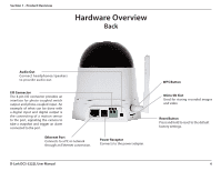
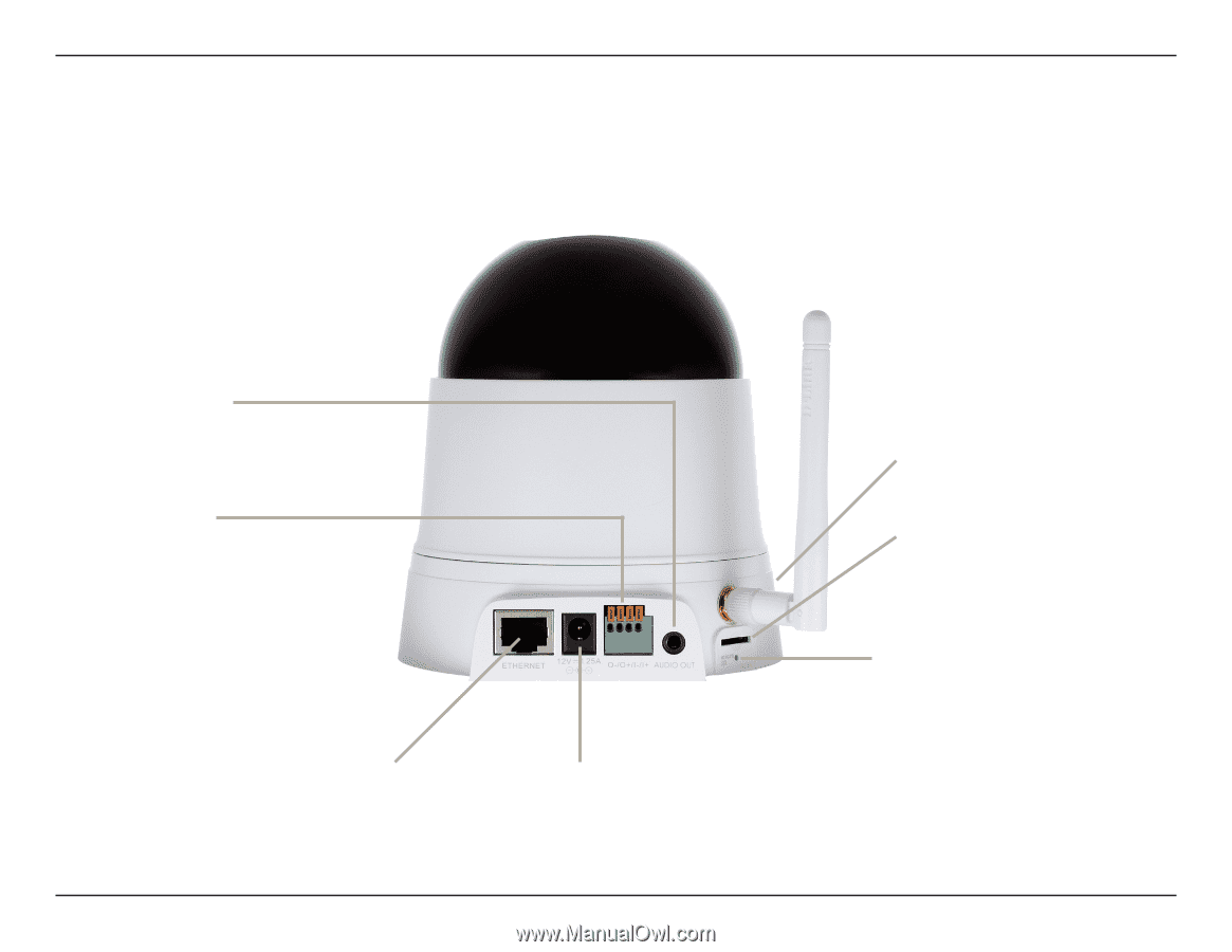
Section 1 - Product Overview Hardware Overview Back Audio Out Connect headphones/speakers to provide audio out. I/O Connector The 4-pin I/O connector provides an interface for photo-coupled switch output and photo-coupled input. An example of what can be done with a digital input and digital output is the connecting of a motion sensor to the port, signalling the camera to take a snapshot and trigger an alarm connected to the port. Ethernet Port Connects to a PC or network through an Ethernet connection. Power Receptor Connects to the power adapter. WPS Button Micro SD Slot Used for storing recorded images and video Reset Button Press and hold to reset to the default factory settings. D-Link DCS-5222L User Manual 6
-
 1
1 -
2
-
3
-
4
-
5
-
6
-
 7
7 -
 8
8 -
 9
9 -
 10
10 -
 11
11 -
 12
12 -
 13
13 -
 14
14 -
 15
15 -
 16
16 -
 17
17 -
18
-
19
-
20
-
21
-
22
-
23
-
24
-
25
-
26
-
27
-
28
-
29
-
30
-
31
-
32
-
33
-
34
-
35
-
36
-
37
-
38
-
39
-
40
-
41
-
42
-
43
-
44
-
45
-
46
-
47
-
48
-
49
-
50
-
51
-
52
-
53
-
54
-
55
-
56
-
57
-
58
-
59
-
60
-
61
-
62
-
63
-
64
-
65
-
66
 |
 |
6
D-Link DCS-5222L User Manual
Section 1 - Product Overview
Hardware Overview
Back
Power Receptor
Connects to the power adapter.
Ethernet Port
Connects to a PC or network
through an Ethernet connection.
I/O Connector
The 4-pin I/O connector provides an
interface for photo-coupled switch
output and photo-coupled input. An
example of what can be done with
a digital input and digital output is
the connecting of a motion sensor
to the port, signalling the camera to
take a snapshot and trigger an alarm
connected to the port.
Audio Out
Connect headphones/speakers
to provide audio out.
Reset Button
Press and hold to reset to the default
factory settings.
WPS Button
Micro SD Slot
Used for storing recorded images
and video