D-Link DFE-855 Manual - Page 15
Table 2- 1, Table 2- 2
 |
UPC - 790069213151
View all D-Link DFE-855 manuals
Add to My Manuals
Save this manual to your list of manuals |
Page 15 highlights
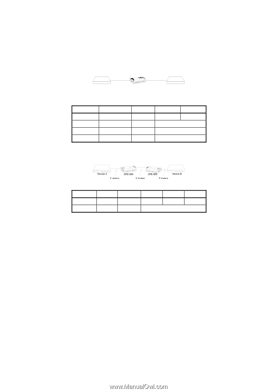
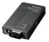
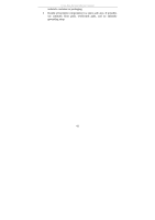
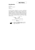
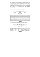
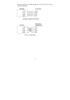
cable; a device with a 100BASE-FX port is connected to the DFE-855's SC jack through a fiber-optic cable; and the supplied AC power adapter is connected to the DFE-855's DC power jack. The figure shows the maximum possible distance between the two devices: 2,100 meters. Note that the network ports on both devices must be explicitly set to full-duplex mode to allow the use of a cable of up to 2,000 meters long on the 100BASE-FX side. In the following figure, device B has a fiber optic port. Device A Max. distance Max. distance X meters Y meters DFE-855 Device B Figure 2- 2 Mode Device A Device B X Y Full-duplex Half-duplex Half-duplex Half-duplex DTE(*) DTE Class I Hub(+) Class II Hub(+) DTE DTE DTE DTE 100m 2000m X ≤ 100, X + Y ≈ 300 X ≤ 100, X + Y ≈ 75 X ≤ 100, X + Y ≈118 Table 2- 1 In the following figure, device B does not have a fiber optic port. Figure 2- 3 Mode Full-duplex Half-duplex Device A DTE(*) DTE Device B X Y Z DTE DTE 100m 2000m 100m X ≤ 100, X + Y +Z ≈ 230 , Z ≤ 100 Table 2- 2 5
-
 1
1 -
2
-
3
-
4
-
5
-
6
-
7
-
8
-
9
-
 10
10 -
 11
11 -
 12
12 -
 13
13 -
 14
14 -
 15
15 -
 16
16 -
 17
17 -
 18
18 -
 19
19 -
 20
20 -
21
-
22
-
23
-
24
-
25
-
26
-
27
-
28
-
29
-
30
-
31
 |
 |