D-Link DFE-855 Manual - Page 18
Appendix B
 |
UPC - 790069213151
View all D-Link DFE-855 manuals
Add to My Manuals
Save this manual to your list of manuals |
Page 18 highlights
Appendix B RJ-45 Pin Specifications The following diagram and table show the standard RJ-45 connector and their pin assignments. The standard RJ-45 connector RJ-45 Connector pin assignment Contact Media Direct Interface Signal 1 TX + (transmit) 2 TX - (transmit) 3 RX + (receive) 4 Not used 5 Not used 6 RX - (receive) 7 Not used 8 Not used 8
-
 1
1 -
2
-
3
-
4
-
5
-
6
-
7
-
8
-
9
-
10
-
11
-
12
-
 13
13 -
 14
14 -
 15
15 -
 16
16 -
 17
17 -
 18
18 -
 19
19 -
 20
20 -
 21
21 -
 22
22 -
 23
23 -
24
-
25
-
26
-
27
-
28
-
29
-
30
-
31
 |
 |

8
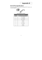
Appendix B
RJ-45 Pin Specifications
The following diagram and table show the standard RJ-45 connector and
their pin assignments.
The standard RJ-45 connector
RJ-45 Connector pin assignment
Contact
Media Direct Interface Signal
1
TX + (transmit)
2
TX - (transmit)
3
RX + (receive)
4
Not used
5
Not used
6
RX - (receive)
7
Not used
8
Not used