D-Link DGS-1024TG User Guide - Page 13
Connecting The Switch
 |
View all D-Link DGS-1024TG manuals
Add to My Manuals
Save this manual to your list of manuals |
Page 13 highlights
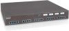
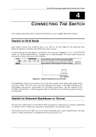
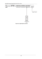
DGS-1024T Unmanaged Gigabit Ethernet Switch User's Guide 4 4 CONNECTING THE SWITCH This chapter describes how to connect the Switch to your Gigabit Ethernet network. Switch to End Node End nodes include PCs outfitted with a 10, 100 or 10/100 Mbps RJ-45 Ethernet/Fast Ethernet Network Interface Card (NIC) and most routers. An end node can be connected to the Switch via a two-pair Category 3, 4, 5, or 5e UTP/STP cable-for optimal performance, Category 5e is recommended. The end node should be connected to any of the ports of the Switch. Figure 4-1. Switch connected to an end node The Link/Act LEDs on the bottom row of the front panel of the device light green when the link is valid. The LED on the top row indicates port speed. It will light solid green for 1000 Mbps connections, solid amber for 100 Mbps connections, and will remain off for 10 Mbps connections. A blinking green LED on the bottom row indicates packet activity on that port. Switch to Network Backbone or Server The two mini GBIC ports on the DGS-1024T are ideal for uplinking to a network backbone or network server. These ports operate at 1000 Mbps in full-duplex mode. Connections to the mini GBIC ports are made using fiber optic cable, depending on the type of port. A valid connection is indicated when the Link LED is lit. 9
-
 1
1 -
2
-
3
-
4
-
5
-
6
-
7
-
 8
8 -
 9
9 -
 10
10 -
 11
11 -
 12
12 -
 13
13 -
 14
14 -
 15
15 -
 16
16 -
 17
17 -
 18
18 -
19
-
20
-
21
-
22
-
23
-
24
-
25
-
26
-
27
 |
 |
