D-Link DGS-1510-52XMP Hardver Install Guide - Page 24
Installing the RPS into a Rack-mount Chassis, DPS-700 - firmware
 |
View all D-Link DGS-1510-52XMP manuals
Add to My Manuals
Save this manual to your list of manuals |
Page 24 highlights
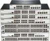
DGS-1510 Series Gigabit Ethernet SmartPro Switch Hardware Installation Guide Installing the RPS into a Rack-mount Chassis The DPS-700 is a redundant power supply unit designed to conform to the voltage requirements of the switches being supported. The DPS-700 can only be used with the DGS-1510-52XMP. CAUTION: DO NOT connect the RPS to AC power before the DC power cable is connected. This might damage the internal power supply. ATTENTION: Ne branchez pas le RPS sur le courant alternatif avant que le câble d'alimentation en courant continu ne soit branché. Cela pourrait endommager l'alimentation électrique interne. DPS-700 The DPS-700 is connected to the Master Switch using a 22-pin DC power cable. A standard, threepronged AC power cable connects the redundant power supply to the main power source. Figure 2-10 Front view of the DPS-700 1. Insert one end of the 22-pin DC power cable into the receptacle on the Switch and the other end into the Redundant Power Supply unit. 2. Using a standard AC power cable, connect the redundant power supply to the main AC power source. A green LED on the front of the DPS-700 will glow to indicate a successful connection. 3. Re-connect the Switch to the AC power source. The LED indicator will show that a redundant power supply is now in operation. 4. No configuration in the Switch's firmware is needed for this installation. NOTE: See the RPS Quick Installation Guide for more information. 24
-
 1
1 -
2
-
3
-
4
-
5
-
6
-
7
-
8
-
9
-
10
-
11
-
12
-
13
-
14
-
15
-
16
-
17
-
18
-
 19
19 -
 20
20 -
 21
21 -
 22
22 -
 23
23 -
 24
24 -
 25
25 -
 26
26 -
 27
27 -
 28
28 -
 29
29 -
30
-
31
-
32
-
33
-
34
-
35
-
36
-
37
-
38
-
39
-
40
-
41
-
42
-
43
-
44
-
45
-
46
-
47
-
48
-
49
-
50
-
51
-
52
-
53
-
54
-
55
-
56
-
57
-
58
-
59
-
60
-
61
-
62
-
63
-
64
-
65
-
66
-
67
-
68
 |
 |
