D-Link DGS-1520-28MP Product Manual 2 - Page 33
Web Interface Navigation, Area Number, Function, AREA 1
 |
View all D-Link DGS-1520-28MP manuals
Add to My Manuals
Save this manual to your list of manuals |
Page 33 highlights
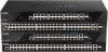
DGS-1520 Series Gigabit Ethernet Smart Managed Switch Hardware Installation Guide Web Interface Navigation After accessing the Web UI, the following will be displayed: AREA 1 AREA 2 AREA 3 AREA 4 Figure 5-4 Web User Interface Areas The Web UI is divided into four distinct areas that are described in the table below: Area Number Function AREA 1 In this area, a graphical near real-time image of the front panel of the Switch is displayed with ports and expansion modules. Some management functions like port monitoring are also accessible here. Click the D-Link logo to go to the D-Link website. AREA 2 In this area, a toolbar with access to functions like Save, Tools, Online Help, customized Language preferences, and a Logout option is available. The user account and IP address, currently accessing the Web UI, is displayed on the right in this toolbar. AREA 3 In this area, the software features available in the Web UI are grouped into folders containing hyperlinks that will open window frames in Area 4. There is also a search option in this area that can be used to search for specific feature keywords in the Web UI to easily find the link to the set of features. AREA 4 In this area, configuration and monitoring window frames are available based on the selections made in Area 3. 28
-
 1
1 -
2
-
3
-
4
-
5
-
6
-
7
-
8
-
9
-
10
-
11
-
12
-
13
-
14
-
15
-
16
-
17
-
18
-
19
-
20
-
21
-
22
-
23
-
24
-
25
-
26
-
27
-
 28
28 -
 29
29 -
 30
30 -
 31
31 -
 32
32 -
 33
33 -
 34
34 -
 35
35 -
 36
36 -
 37
37 -
 38
38 -
39
-
40
-
41
-
42
-
43
-
44
-
45
-
46
-
47
-
48
-
49
-
50
-
51
-
52
-
53
-
54
-
55
-
56
-
57
-
58
-
59
-
60
-
61
-
62
 |
 |
