D-Link DGS-3224TGR Product Manual - Page 19
Front Panel, Rear Panel
 |
UPC - 790069261244
View all D-Link DGS-3224TGR manuals
Add to My Manuals
Save this manual to your list of manuals |
Page 19 highlights
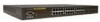
DGS-3224TGR Gigabit Ethernet Switch User's Guide 3 Identifying External Components This chapter describes the front panel, rear panel, side panels, and LED indicators of the DGS-3224TGR. Front Panel The front panel of the switch consists of LED indicators, an RS-232 communication port, 24 1000BASE-T ports, and 4 mini-GBIC combo ports. Figure 3-1. Front panel view • An RS-232 DCE console port for setting up and managing the switch via a connection to a console terminal or PC using a terminal emulation program. • Comprehensive LED indicators display the status of the switch and the network (see the LED Indicators section below). • Twenty-four 1000BASE-T Ethernet ports for 10/100/1000 connections to a backbone, end stations, and servers. • Four mini-GBIC combo ports to connect fiber optic media to another switch, server, or network backbone. Rear Panel The rear panel of the switch contains an external Redundant Power Supply connector and an AC power connector. Figure 3-2. Rear panel view • The external Redundant Power Supply connector is used to connect the DGS-3224TGR to a DPS-300. An auto-switch circuit automatically switches to an external RPS once the internal power supply fails. Transition from internal to external supply shall not disturb normal operation. • The AC power connector is a standard three-pronged connector that supports the power cord. Plug-in the female connector of the provided power cord into this socket, and the male side of the cord into a power outlet. Supported input voltages range from 100 ~ 240 VAC at 50 ~ 60 Hz. 7
-
 1
1 -
2
-
3
-
4
-
5
-
6
-
7
-
8
-
9
-
10
-
11
-
12
-
13
-
 14
14 -
 15
15 -
 16
16 -
 17
17 -
 18
18 -
 19
19 -
 20
20 -
 21
21 -
 22
22 -
 23
23 -
 24
24 -
25
-
26
-
27
-
28
-
29
-
30
-
31
-
32
-
33
-
34
-
35
-
36
-
37
-
38
-
39
-
40
-
41
-
42
-
43
-
44
-
45
-
46
-
47
-
48
-
49
-
50
-
51
-
52
-
53
-
54
-
55
-
56
-
57
-
58
-
59
-
60
-
61
-
62
-
63
-
64
-
65
-
66
-
67
-
68
-
69
-
70
-
71
-
72
-
73
-
74
-
75
-
76
-
77
-
78
-
79
-
80
-
81
-
82
-
83
-
84
-
85
-
86
-
87
-
88
-
89
-
90
-
91
-
92
-
93
-
94
-
95
-
96
-
97
-
98
-
99
-
100
-
101
-
102
-
103
-
104
-
105
-
106
-
107
-
108
-
109
-
110
-
111
-
112
-
113
-
114
-
115
-
116
-
117
-
118
-
119
-
120
-
121
-
122
-
123
-
124
-
125
-
126
-
127
-
128
-
129
-
130
-
131
-
132
-
133
-
134
-
135
-
136
-
137
-
138
-
139
-
140
-
141
-
142
-
143
-
144
-
145
-
146
-
147
-
148
-
149
-
150
-
151
-
152
-
153
-
154
-
155
-
156
-
157
-
158
-
159
-
160
 |
 |
