D-Link DGS-3630 Quick Install Guide - Page 35
See the RPS Quick Installation Guide for more information., Redundant Power Supply unit.
 |
View all D-Link DGS-3630 manuals
Add to My Manuals
Save this manual to your list of manuals |
Page 35 highlights
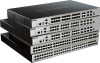
DGS-3630 Series Layer 3 Stackable Managed Switch Hardware Installation Guide Figure 3-11 Front view of the DPS-700 1. Insert one end of the 22-pin DC power cable into the receptacle on the Switch and the other end into the Redundant Power Supply unit. 2. Using a standard AC power cable, connect the redundant power supply to the main AC power source. A green LED on the front of the DPS-700 will glow to indicate a successful connection. 3. Re-connect the Switch to the AC power source. The LED indicator will show that a redundant power supply is now in operation. 4. No configuration in the Switch's firmware is needed for this installation. NOTE: See the RPS Quick Installation Guide for more information. Figure 3-12 Rear view of the DPS-700 connected to a DGS-3120-24PC 35
-
 1
1 -
2
-
3
-
4
-
5
-
6
-
7
-
8
-
9
-
10
-
11
-
12
-
13
-
14
-
15
-
16
-
17
-
18
-
19
-
20
-
21
-
22
-
23
-
24
-
25
-
26
-
27
-
28
-
29
-
 30
30 -
 31
31 -
 32
32 -
 33
33 -
 34
34 -
 35
35 -
 36
36 -
 37
37 -
 38
38 -
 39
39 -
 40
40 -
41
-
42
-
43
-
44
-
45
-
46
-
47
-
48
-
49
-
50
-
51
-
52
-
53
-
54
-
55
-
56
-
57
-
58
-
59
-
60
-
61
-
62
-
63
-
64
-
65
-
66
-
67
-
68
-
69
-
70
-
71
-
72
-
73
-
74
-
75
-
76
-
77
-
78
-
79
-
80
-
81
-
82
-
83
 |
 |
