D-Link DIS-100E-5W Quick Installation Guide - Page 2
DIN-Rail Mounting, Wall Mounting, Connecting to Ground, Connecting to Ethernet Interfaces, RJ-45
 |
View all D-Link DIS-100E-5W manuals
Add to My Manuals
Save this manual to your list of manuals |
Page 2 highlights
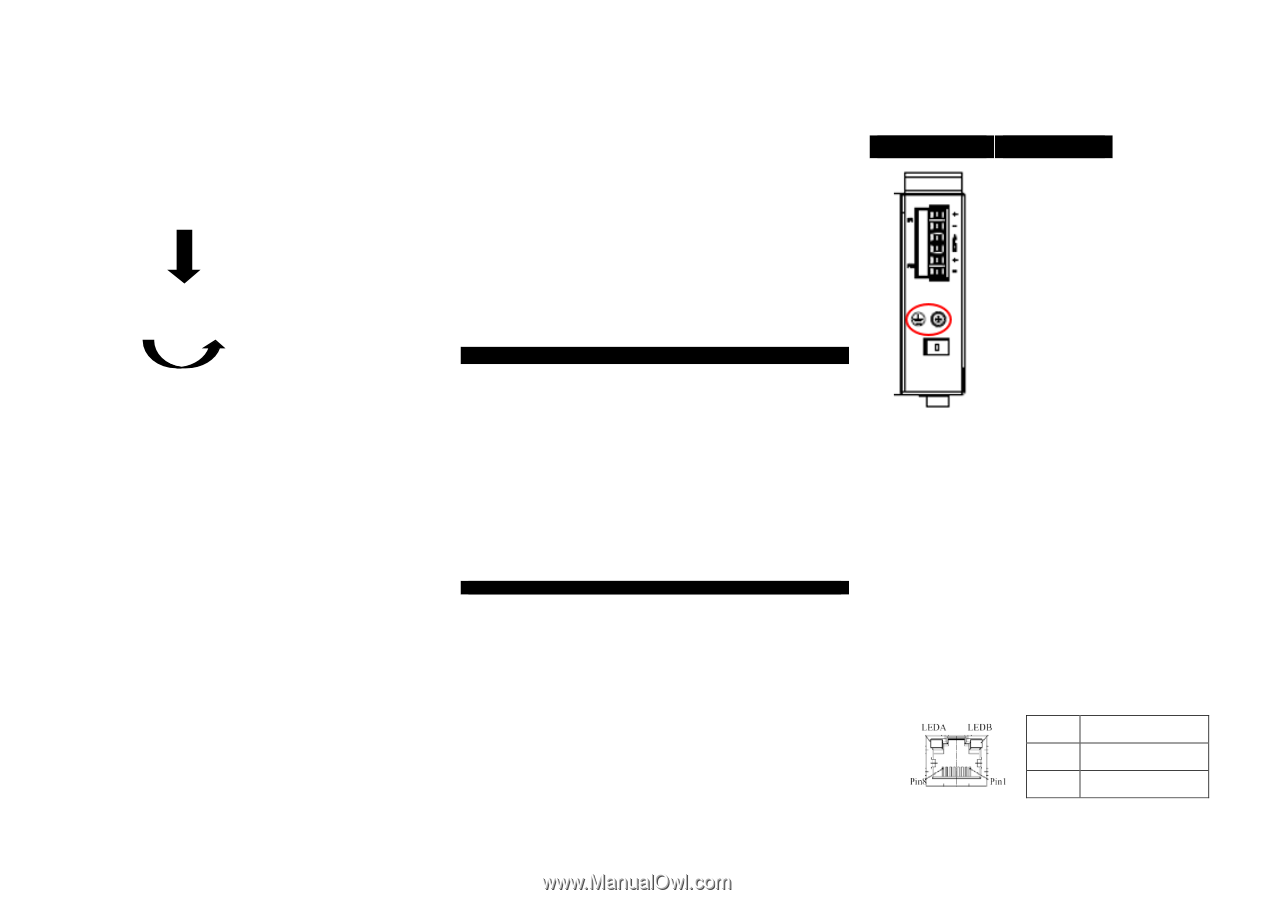
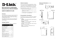
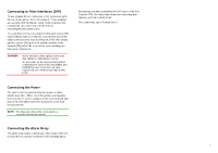
DIN-Rail Mounting 1. Attach the DIN rail kit onto the switch using the bracket and screws in the accessory kit. 2. Hook the unit over the DIN rail. 3. Push the bottom of the unit towards the DIN rail until it snaps into place. 2 Wall Mounting (unit: mm) 1. Attach the wall mounting kit onto the switch using the mounting plates and M4 screws in the accessory kit. Connecting to Ground The switch must be properly grounded for optimum system performance. 5-Port Model 8-Port Model 3 Ver. 1.00(WW) 2018/06/06 GP801010X-000 5-Port Model 8-Port Model Connecting to Ethernet Interfaces (RJ-45) Connecting the Ethernet interface via RJ-45: To connect to a PC, use a straight-through or a cross-over Ethernet cable, To connect the switch to an Ethernet device, use UTP (Unshielded Twisted Pair) or STP (Shielded Twisted Pair) Ethernet cables. The pin assignment of the RJ-45 connector is shown in the following figure and table. Pin Assignment 1,2 T/Rx+,T/Rx- 3,6 R/Tx+,R/Tx- 2
-
 1
1 -
 2
2 -
 3
3 -
 4
4 -
 5
5 -
 6
6 -
 7
7 -
 8
8
 |
 |