D-Link DP-301 Product Manual - Page 11
Power-up and Self-Test, LED Test Series, Component Test Series - d link
 |
UPC - 790069262579
View all D-Link DP-301 manuals
Add to My Manuals
Save this manual to your list of manuals |
Page 11 highlights
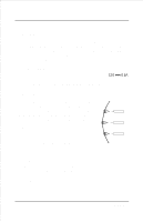
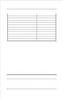
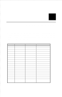
DP-301 Print Server Hardware Guide Power-up and Self-Test Whenever the DP-301 is powered up, two kinds of testing procedures follow automatically. The first procedure is just a programmed series of LED flashes, to confirm proper operation of the three LED indicators. The second procedure comprises programmed tests of each of the DP-301's major components. If any fault is found during the component test series, testing is halted and a continuous pattern of LED flashes signals the nature of the fault. LED Test Series Immediately upon power-up, all three of the LED indicators will show steady green for several seconds. Then the LPT indicator will flash three times while Pw/Tx and Link/Rx remain steady. Irregularity of any of the LEDs during this LED test series indicates that there is a problem with the LEDs themselves. Contact your dealer for correction of any LED problems before proceeding. Component Test Series The actual component tests immediately follow the LED tests. A normal (no fault) result is signaled by three flashes of the LPT indicator and the start of normal print server operation. If any error condition is found during the component test series, then the test will halt with the LPT LED continuously signaling the particular error according to the following table. LPT Flash Pattern 8 Error Type Unpacking and Installation
-
 1
1 -
2
-
3
-
4
-
5
-
 6
6 -
 7
7 -
 8
8 -
 9
9 -
 10
10 -
 11
11 -
 12
12 -
 13
13 -
 14
14 -
 15
15 -
 16
16 -
17
-
18
-
19
-
20
-
21
 |
 |