D-Link DPE-301GS Datasheet 1.00 - Page 2
DPE-301GI / DPE-301GS
 |
View all D-Link DPE-301GS manuals
Add to My Manuals
Save this manual to your list of manuals |
Page 2 highlights
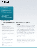
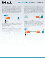
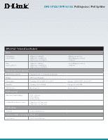
DPE-301GI / DPE-301GS PoE Injector / PoE Splitter 10/100/1000 RJ-45 ports. One port is for LAN IN, which is the network connection, typically connected to a non-PoE switch or router. The other port is for PoE OUT, which is the connection that provides both power and data signal to the end device (PD). The DPE-301GI can be located anywhere on the Ethernet link, although it's typically placed near the switch/router. Location of the injector does not impact the maximum 100m (328ft.) distance from the switch/router to the end device. non-PoE Switch or Router LAN IN 54V IN DPE-301GI PoE OUT 54VDC Power Adapter PoE Powered Device (PD) Support for IEEE 802.3at ensures the DPE-301GI can power PoE+ devices up to 30W, such as high power 802.11ac APs and IP cameras with PTZ motors, heaters and blowers. DPE-301GS Gigabit PoE Splitter The DPE-301GS PoE splitter is used with end devices such as wireless access points, IP cameras and VoIP phones that don't natively support PoE, but rather require DC power input of 5V, 9V or 12V. It receives PoE power on a network cable from a PoE switch or midspan injector, and splits the Ethernet and DC power into two separate cables. One cable provides the DC power, and the other cable provides the Ethernet signal. Users can select from 5VDC, 9VDC and 12VDC power for their device using a selectable DIP switch on the device. The DPE-301GS PoE splitter is typically located near the end device. It has two 10/100/1000 RJ-45 ports. One port is for PoE IN, which is the network connection and is usually connected to a remote PoE switch or injector. The other port is for LAN OUT, which is the connection that provides the Ethernet signal to the end device. The DPE-301GS also has a 5.5mm DC OUT port. Two adapter cables are supplied; either one may be connected to this port, depending on whether 5.5mm or 3.8mm interface is required for the end device. PoE Switch or Injector LAN OUT PoE IN DPE-301GS DC OUT PoE Injector and PoE Splitter Tandem non-PoE Device Both the DPE-301GI and DPE-301GS can be used together, as a complete PoE transport system. This is especially useful when a PoE switch is not available, and the end device is not PoE capable, but the Network Administrator still prefers the benefits of PoE. Simply install the injector close to the network switch, install the splitter close to the end device, and plug in the cables. non-PoE Switch or Router LAN IN DPE-301GI PoE OUT 54V IN 54VDC Power Adapter LAN OUT PoE IN DPE-301GS DC OUT non-PoE Device
-
 1
1 -
 2
2 -
 3
3 -
 4
4 -
 5
5
 |
 |
