D-Link DSR-250v2 Quick installation guide - Page 1
D-Link DSR-250v2 Manual
 |
View all D-Link DSR-250v2 manuals
Add to My Manuals
Save this manual to your list of manuals |
Page 1 highlights
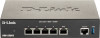
Quick Installation Guide Unified Services Router This document will guide you through the basic installation process for your new D-Link Unified Services Router. DSR-250V2 About This Guide This guide gives step by step instructions for setting up D-Link DSR-250V2 Services Router. Please note that the model you have purchased may appear slightly different from those shown in the illustrations. Unpacking the Product Open the shipping carton and carefully unpack its contents. Please consult the packing list located in following information to make sure all items are present and undamaged. If any item is missing or damaged, please contact your local D-Link reseller for replacement. - One (1) DSR-250V2 Unified Services Router Appliance - One (1) 12V/1.5A Power Adapter - One (1) Console Cable (RJ45-to-DB9 Cable) - One (1) Ethernet (CAT5 UTP/Straight Through) Cable Product Overview This chapter provides detailed descriptions of the DSR-250V2 device and its components. Front Panel A C D EB Figure 1. DSR-250V2 Front Panel Item Feature Description A LED (Top to bottom) Power LED: Indicates the Services Router is powered on. B USB Port (1) It can support various USB 2.0, 3.0 devices below: 1.Flash Disk or Hard Disk for network sharing. 2.Printer (It will be supported by future firmware upgrade) C Gigabit LAN port (1-4) Connect Ethernet devices, such as computers, switches and hubs. D Gigabit WAN port (1) One auto MDI/MDIX WAN ports are the connection for the Ethernet cable to the cable or DSL modem. E Console Port (1) Used to access Command Line Interface (CLI) via RJ45-to-DB9 console Cable. Table 1: DSR-250V2 Front Panel Descriptions Device Status LEDs and Ethernet Port LEDs Link Speed TX/RX Status Figure 2. Ethernet RJ-45 Port LEDs The device LEDs show information about current device status. When the device power up, the POWER/STATUS LED will show solid orange during power on process. Startup takes one minute approximately to complete, the LED will change to solid green. If you want to turn the device off and on again, we recommend you wait a few seconds between shutting it down and powering it back. The Ethernet LEDs show the status of each Ethernet port. Table 2 lists the name, color, status and description of each device LED. LED Indicators Color Status Description Power / Status Orange/Green/Red Solid Orange Device during power-on process Solid Green Solid Red Completion of power on Factory Reset TX/RX Status Green LINK Speed Green/Orange Blinking Red Light Off Light Off Solid Green Blinking Green Solid Orange Solid Orange Solid Green Firmware upgrade The device is power-off No Link. Link present. Port is sending or receiving data. Port is operating at 10Mbps. Port is operating at 100Mbps Port is operating at 1000Mbps Table 2: Device Status LED Descriptions DSR-250V2 Default Interface Settings Ethernet Interface Interface Type IP Address Web-Based Management DHCP Server LAN(1-4) Static IP 192.168.10.1 Enabled Enabled WAN DHCP Client 0.0.0.0 Disabled Disabled Table 3: Default Interface Settings Note: D-Link Services Routers only allow Web GUI access from LAN interfaces by default for security reason. Installing and Connecting the Device This chapter describes how to connect cables and power to the device. Before You Begin Observe the following precautions to help prevent shutdowns, equipment failures and injuries: - Before installation, always check that the power supply is disconnected - Ensure that the room in which you operate the device has adequate air circulation and that the room temperature does Not exceed 40˚C (104˚F) - Allow 3 inch of clear space to the front and back of the device. - Do not place the device in an equipment rack frame that blocks the air vents on the sides of the chassis. Ensure that enclosed racks have fans and louvered sides. - Correct these hazardous conditions before any installation: moist or wet floors, leaks, ungrounded or frayed power cables, or missing safety grounds. Connecting Power and Turn the Device On/Off The AC/DC Power Adapter shipped with the device connects the device to earth ground when plugged an AC grounding-type power outlet. The device must be connected to earth ground during normal operation. To connect power to the device, plug the AC/DC power adapter into the DC power phone jet on the back panel of the device. Note: We recommend using a surge protector for the power connection. To power on the DSR-250V2 device, press the DC power switch on the rear panel to the on position. To power off the device, press the power switch to the off position. Connecting the Device to a Network This section provides basic information about physically connecting the DSR-250V2 to a network. To connect the necessary cables as shown in Figure 3. 1. Connect an RJ-45 cable from the port labeled WAN to the external router. The port WAN is pre-allocated to the WAN network segment. v1.01(WW)_90x130 2023/02/22 2907260025V2B11
-
 1
1 -
 2
2
 |
 |