D-Link DSS-100E-9P Quick Install Guide 3 - Page 3
DIP Switches, Hardware Installation - 18p manual
 |
View all D-Link DSS-100E-9P manuals
Add to My Manuals
Save this manual to your list of manuals |
Page 3 highlights
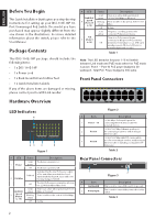
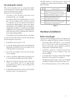
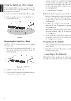
ENGLISH Grounding the Switch This section describes how to connect the switch to the ground. You must complete this procedure before powering on the switch. Required Tools and Equipment: • One M4 x 6 mm (metric) pan-head screw (included in the accessory kit). • Grounding cable (not included in the accessory kit): The grounding cable should be sized according to local and national installation requirements. Depending on the power supply and system, a 12 to 6 AWG copper conductor is required for installation. Commercially available 6 AWG wire is recommended. The length of the cable depends on the proximity of the switch to proper grounding facilities. • A screwdriver (not included in the accessory kit). You can connect the switch to a protective ground by following the steps below: 1. Verify if the system power is off. 2. Use the grounding cable to place the #8 terminal lug ring (not included in the accessory kit) on top of the ground-screw opening. 3. Insert the grounding screw into the ground screw opening. DIP Switches 5 6 7 85 6 7 8 15 26 37 48 1 5 26 37 48 The DIP switches on the front panel allow easy configuration of the advanced features of the DSS-100E-18P DIP Switch Function Controlled Standard Switch all ports can communicate with each other port and work as a common Unmanaged Switch. *1 to 16 port supports Power over Ethernet and transmit data at 10/100 Mbps.** 1 to 8 port supports port priority to optimize port cache. Isolate 1 to 16 port can't communicate with each other, but each of them can communicate with port 17 and 18. Extend The data rate of 9 to 16 port is limited to 10Mbps, whereas the maximum transmission distance of the port is increased to 250 meters. Default On Off Off Table 4 4. Using a screwdriver, tighten the grounding screw Hardware Installation to secure the grounding cable to the switch. 5. Attach the terminal lug ring at the other end of the grounding cable to an appropriate grounding stud or bolt on the rack where the switch is installed. 6. Verify that the ground connections on the switch and the rack are securely attached. Before You Begin Observe the following precautions to help prevent shutdowns, equipment failures, and personal injury: • Install the DSS-100E-18P in a cool and dry place. Refer to the technical specifications in the user manual for the acceptable operating temperature and humidity ranges. • Install the switch in a site free from strong electromagnetic sources, vibration, dust, and direct sunlight. • Leave at least 10 cm of space to the left and righthand side of the switch for ventilation. • Visually inspect the power connector and make sure that it is fully secured to the power cord. • Do not stack any devices on top of the switch. 3
-
 1
1 -
 2
2 -
 3
3 -
 4
4 -
 5
5 -
 6
6
 |
 |
