D-Link DSS-100E-9P Quick Install Guide 3 - Page 4
Using the Switch on a Flat Surface, Mounting the Switch in a Rack, Grounding the Switch, Powering
 |
View all D-Link DSS-100E-9P manuals
Add to My Manuals
Save this manual to your list of manuals |
Page 4 highlights
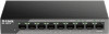
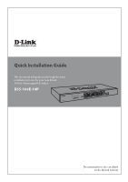
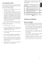
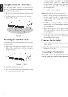
ENGLISH Using the Switch on a Flat Surface The included rubber pads can be placed on the bottom of the device to prevent it from damaging the surface it is placed on. 1. Remove the rubber pads from the adhesive strip. 2. Stick one pad on each corner on the bottom panel of the switch. Figure 4 Mounting the Switch in a Rack The DSS-100E-18P can be mounted into a standard 19" server rack. 1. Attach the included mounting brackets to the sides of the switch and secure them using the provided screws. Figure 5 2. Install the switch into the rack. 3. Use the screws that were provided with the rack to secure the switch to the rack. Grounding the Switch This step must be completed before powering on the switch. Required tools and equipment for grounding • Grounding screw (included) and one M4x6 (metric) pan-head screw (not included). • Grounding cable (not included). The grounding cable should be sized according to local and national installation requirements. Depending on the power supply and system, a 12 to 6 AWG copper conductor is required for installation. Commercially available 6 AWG wire is recommended. The length of the cable depends on the proximity of the switch to proper grounding facilities. • A screwdriver (not included). Note: Verify that the system is powered off. 1. Remove the grounding screw from the back of the device and place the #8 terminal lug ring of the grounding cable on top of the grounding screw opening. 2. Insert the grounding screw back into the screw opening and use a screwdriver to tighten the grounding screw. 3. Attach the terminal lug ring at the other end of the grounding cable to an appropriate grounding source. 4. Verify that the connection between the grounding connector on the switch and the grounding source is secure. Powering On the Switch 1. Connect the power cord to the power connector on the switch. 2. Plug the other end of the power cord into a nearby power socket. Connecting to the Network The switch can be integrated into the network through one of the following connection methods: Figure 6 4
-
 1
1 -
 2
2 -
 3
3 -
 4
4 -
 5
5 -
 6
6
 |
 |