D-Link DSS-200G-10MPP Product Manual - Page 15
Rear Panel, Description, Power, CAUTION
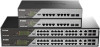 |
View all D-Link DSS-200G-10MPP manuals
Add to My Manuals
Save this manual to your list of manuals |
Page 15 highlights
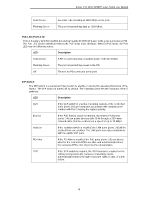
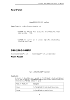
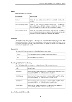
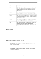
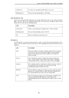
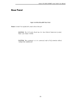
LED QoS Extend Isolation PD-Alive STP D-Link DSS-200G MP/MPP series Switch User Manual Description If the QoS switch is enabled, incoming packets of the controlled ports (ports 1-24) are forwarded according to the port priority based on the assigned port number (with Port 1 having the highest priority). If the PoE Extend switch is enabled, the enabled PoE ports (ports 1-4) can power devices with 20 W through a 250-meter network cable (Cat 5e or above) at a speed of up to 10 Mbps. If the Isolation switch is enabled, the LAN ports (ports 1-8) will be isolated from one another. The LAN ports can only communicate with the uplink SFP ports. If the PD-Alive is enabled, the PoE ports (ports 1-8) can detect whether the connected PDs are alive and automatically reboot the connected PDs once they become unresponsive. If the STP switch is enabled, the STP function is enabled on the uplink ports (ports 9-10). Network connectivity can be automatically restored through redundant paths in case of a link failure. Rear Panel Figure 2-4 DSS-200G-10MPP Rear Panel Power: Connect the supplied AC power cable to this port. CAUTION: The SFP ports should use UL listed Optical Transceiver product, Rated Laser Class I. 3.3Vdc. CAUTION: This equipment is to be connected only to PoE networks without routing to the outside plant. 10
-
 1
1 -
2
-
3
-
4
-
5
-
6
-
7
-
8
-
9
-
 10
10 -
 11
11 -
 12
12 -
 13
13 -
 14
14 -
 15
15 -
 16
16 -
 17
17 -
 18
18 -
 19
19 -
 20
20 -
21
-
22
-
23
-
24
-
25
-
26
-
27
-
28
-
29
-
30
-
31
-
32
-
33
-
34
-
35
-
36
-
37
-
38
-
39
-
40
-
41
-
42
-
43
-
44
-
45
-
46
-
47
-
48
-
49
-
50
-
51
-
52
-
53
-
54
-
55
-
56
-
57
-
58
-
59
-
60
-
61
-
62
-
63
-
64
-
65
-
66
-
67
-
68
-
69
-
70
-
71
-
72
-
73
-
74
-
75
-
76
-
77
-
78
-
79
-
80
-
81
-
82
-
83
-
84
-
85
-
86
-
87
-
88
-
89
-
90
-
91
-
92
-
93
-
94
-
95
-
96
-
97
-
98
-
99
-
100
-
101
-
102
-
103
-
104
-
105
-
106
-
107
-
108
-
109
-
110
-
111
-
112
-
113
-
114
-
115
-
116
-
117
-
118
-
119
-
120
-
121
-
122
-
123
-
124
-
125
-
126
-
127
-
128
-
129
-
130
-
131
-
132
-
133
-
134
-
135
-
136
 |
 |