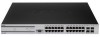
D-Link DWS-3024L User Manual - Page 9

List of s - d link dws 3024

Page 9 highlights

List of Figures List of Figures Figure 1. Sample WLAN Visualization 23 Figure 2. Single Unified Switch with Layer 2 Roaming Support 24 Figure 3. Peer Unified Switch with Layer 3 Roaming Support 25 Figure 4. Web Interface Layout 26 Figure 5. Cascading Navigation Menu 27 Figure 6. Hierarchical Tree Navigation Menu 27 Figure 7. D-Link Unified Access System Components 34 Figure 8. Wiring Closet Topology 35 Figure 9. Data Center Topology 36 Figure 10. Inter-Subnet Roaming 38 Figure 11. Front Panel View of the DWS-3024L as Shipped 40 Figure 12. Front Panel View of the DWS-3024 as Shipped 40 Figure 13. Front Panel View of the DWS-3026 as Shipped 40 Figure 14. LED Indicators on DWS-3024L 41 Figure 15. LED Indicators on DWS-3024 41 Figure 16. LED Indicators on DWS-3026 41 Figure 17. Rear panel view of DWS-3024/DWS-3024L 43 Figure 18. Rear panel view of DWS-3026 43 Figure 19. Prepare Switch for Installation on a Desktop or Shelf 45 Figure 20. Fasten Mounting Brackets to Switch 45 Figure 21. Mounting the Switch in a Standard 19" Rack 46 Figure 22. Inserting the Fiber-Optic Transceivers into the Switch 47 Figure 23. Front Panel of the DEM-410X 48 Figure 24. Front Panel of the DEM-410CX 48 Figure 25. Inserting the optional module into the Switch (DWS-3026 48 Figure 26. DWS-3026 with optional DEM-410X module installed 49 Figure 27. RPS Connector 49 Figure 28. Switch and AP Connected Directly 50 Figure 29. Switch and APs Connected Through Network 51 Figure 30. Switch Connected to Network Core 51 Figure 31. Ethernet Connection for Static IP Assignment 58 Figure 32. L2 Discovery Example 62 Figure 33. L3 Discovery Example 1 62 Figure 34. L3 Discovery Example 2 63 Figure 35. DHCP Option Example 63 Figure 36. Requiring AP Authentication 76 Figure 37. MAC Access Control 86 Figure 38. Radio Settings 88 Figure 39. VAP Settings 93 Figure 40. Configuring Network Settings 95 Figure 41. AP Profile With Five VAPs Enabled 98 Figure 42. Networks Available to the Wireless Client 98 Figure 43. L3 Roaming Example 100 9

  • 1
  • 2
  • 3
  • 4
  • 5
  • 6
  • 7
  • 8
  • 9
  • 10
  • 11
  • 12
  • 13
  • 14
  • 15
  • 16
  • 17
  • 18
  • 19
  • 20
  • 21
  • 22
  • 23
  • 24
  • 25
  • 26
  • 27
  • 28
  • 29
  • 30
  • 31
  • 32
  • 33
  • 34
  • 35
  • 36
  • 37
  • 38
  • 39
  • 40
  • 41
  • 42
  • 43
  • 44
  • 45
  • 46
  • 47
  • 48
  • 49
  • 50
  • 51
  • 52
  • 53
  • 54
  • 55
  • 56
  • 57
  • 58
  • 59
  • 60
  • 61
  • 62
  • 63
  • 64
  • 65
  • 66
  • 67
  • 68
  • 69
  • 70
  • 71
  • 72
  • 73
  • 74
  • 75
  • 76
  • 77
  • 78
  • 79
  • 80
  • 81
  • 82
  • 83
  • 84
  • 85
  • 86
  • 87
  • 88
  • 89
  • 90
  • 91
  • 92
  • 93
  • 94
  • 95
  • 96
  • 97
  • 98
  • 99
  • 100
  • 101
  • 102
  • 103
  • 104
  • 105
  • 106
  • 107
  • 108
  • 109
  • 110
  • 111
  • 112
  • 113
  • 114
  • 115
  • 116
  • 117
  • 118
  • 119
  • 120
  • 121
  • 122
  • 123
  • 124
  • 125
  • 126
  • 127
  • 128
  • 129
  • 130
  • 131
  • 132
  • 133
  • 134
  • 135
  • 136
  • 137
  • 138
  • 139
  • 140
  • 141
  • 142
  • 143
  • 144
  • 145
  • 146
  • 147
  • 148
  • 149
  • 150
  • 151
  • 152
  • 153
  • 154
  • 155
  • 156
  • 157
  • 158
  • 159
  • 160
  • 161
  • 162
  • 163
  • 164
  • 165
  • 166
  • 167
  • 168
  • 169
  • 170
  • 171
  • 172
  • 173
  • 174
  • 175
  • 176
  • 177
  • 178
  • 179
  • 180
  • 181
  • 182
  • 183
  • 184
  • 185
  • 186
  • 187
  • 188
  • 189
  • 190
  • 191
  • 192
  • 193
  • 194
  • 195
  • 196
  • 197
  • 198
  • 199
  • 200
  • 201
  • 202
  • 203
  • 204
  • 205
  • 206
  • 207
  • 208
  • 209
  • 210
  • 211
  • 212
  • 213
  • 214
  • 215
  • 216
  • 217
  • 218
  • 219
  • 220
  • 221
  • 222
  • 223
  • 224
  • 225
  • 226
  • 227
  • 228
  • 229
  • 230
  • 231
  • 232
  • 233
  • 234
  • 235
  • 236
  • 237
  • 238
  • 239
  • 240
  • 241
  • 242
  • 243
  • 244
  • 245
  • 246
  • 247
  • 248
  • 249
  • 250
  • 251
  • 252
  • 253
  • 254
  • 255
  • 256
  • 257
  • 258
  • 259
  • 260
  • 261
  • 262
  • 263
  • 264
  • 265
  • 266
  • 267
  • 268

9
List of Figures
List of Figures
Figure 1. Sample WLAN Visualization
................................................................
23
Figure 2. Single Unified Switch with Layer 2 Roaming Support
.........................
24
Figure 3. Peer Unified Switch with Layer 3 Roaming Support
............................
25
Figure 4. Web Interface Layout
............................................................................
26
Figure 5. Cascading Navigation Menu
.................................................................
27
Figure 6. Hierarchical Tree Navigation Menu
......................................................
27
Figure 7. D-Link Unified Access System Components
........................................
34
Figure 8. Wiring Closet Topology
........................................................................
35
Figure 9. Data Center Topology
...........................................................................
36
Figure 10. Inter-Subnet Roaming
.........................................................................
38
Figure 11. Front Panel View of the DWS-3024L as Shipped
..............................
40
Figure 12. Front Panel View of the DWS-3024 as Shipped
.................................
40
Figure 13. Front Panel View of the DWS-3026 as Shipped
.................................
40
Figure 14. LED Indicators on DWS-3024L
..........................................................
41
Figure 15. LED Indicators on DWS-3024
............................................................
41
Figure 16. LED Indicators on DWS-3026
............................................................
41
Figure 17. Rear panel view of DWS-3024/DWS-3024L
......................................
43
Figure 18. Rear panel view of DWS-3026
...........................................................
43
Figure 19. Prepare Switch for Installation on a Desktop or Shelf
........................
45
Figure 20. Fasten Mounting Brackets to Switch
...................................................
45
Figure 21. Mounting the Switch in a Standard 19" Rack
.....................................
46
Figure 22. Inserting the Fiber-Optic Transceivers into the Switch
.......................
47
Figure 23. Front Panel of the DEM-410X
............................................................
48
Figure 24. Front Panel of the DEM-410CX
.........................................................
48
Figure 25. Inserting the optional module into the Switch (DWS-3026)
...............
48
Figure 26. DWS-3026 with optional DEM-410X module installed
.....................
49
Figure 27. RPS Connector
....................................................................................
49
Figure 28. Switch and AP Connected Directly
.....................................................
50
Figure 29. Switch and APs Connected Through Network
....................................
51
Figure 30. Switch Connected to Network Core
....................................................
51
Figure 31. Ethernet Connection for Static IP Assignment
....................................
58
Figure 32. L2 Discovery Example
........................................................................
62
Figure 33. L3 Discovery Example 1
.....................................................................
62
Figure 34. L3 Discovery Example 2
.....................................................................
63
Figure 35. DHCP Option Example
.......................................................................
63
Figure 36. Requiring AP Authentication
..............................................................
76
Figure 37. MAC Access Control
..........................................................................
86
Figure 38. Radio Settings
......................................................................................
88
Figure 39. VAP Settings
.......................................................................................
93
Figure 40. Configuring Network Settings
.............................................................
95
Figure 41. AP Profile With Five VAPs Enabled
..................................................
98
Figure 42. Networks Available to the Wireless Client
.........................................
98
Figure 43. L3 Roaming Example
........................................................................
100