DIRECTV H23 System Manual - Page 107
Satellite In Swm-1, Component Video Out, A/v Out, Rca-audio/video Jacks, Digital Audio Out, Ethernet - usb
 |
View all DIRECTV H23 manuals
Add to My Manuals
Save this manual to your list of manuals |
Page 107 highlights
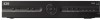
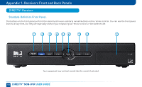
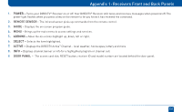
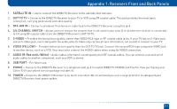
Appendix 1: Receivers Front and Back Panels 1. SATELLITE IN (SWM-1) - Connect one line from your satellite dish here. A Single Wire Multi-Switch (SWM) connection, if applicable, is made to this satellite in port. 2. COMPONENT VIDEO OUT- Some receivers have a block of three separate connectors - green, red, blue. Use this block to connect up HD component video cables and use the white and red RCA connectors below it for analog audio out. A/V OUT - Some newer model receivers have a combined 10-pin output that supports both audio and video. Receivers supporting A/V Out come with an A/V Out cable for Component Video and RCA audio. An A/V Out cable for Composite Video and RCA audio can be purchased separately. 3. RCA-Audio/Video Jacks - A Standard-Definition (SD) output. You can use the entire row of RCA connectors (yellow, white and red) to feed a VCR or DVD player/burner. 4. DIGITAL AUDIO OUT - Use this digital audio connection for sound. Not available on all models. 5. HDMI - Use this combination digital video and audio connector for the best HD picture quality. 6. ETHERNET - For future use. Not available on all models. 7. USB - For future use. (USB 2.0 Host 5V = 500mA) 8. PHONE JACK - Connect your phone line here to enable Pay Per View purchasing and Caller ID (if your phone service package includes it). 9. POWER - Your receiver must be plugged in at all times to function properly. Note that some newer model receivers require an external power supply, while older models plug in through a direct power cord. 10. EXTERNAL REMOTE - Some model receivers support an external adapter for use with an optional RF remote. Other models have RF built-in. 107
-
 1
1 -
2
-
3
-
4
-
5
-
6
-
7
-
8
-
9
-
10
-
11
-
12
-
13
-
14
-
15
-
16
-
17
-
18
-
19
-
20
-
21
-
22
-
23
-
24
-
25
-
26
-
27
-
28
-
29
-
30
-
31
-
32
-
33
-
34
-
35
-
36
-
37
-
38
-
39
-
40
-
41
-
42
-
43
-
44
-
45
-
46
-
47
-
48
-
49
-
50
-
51
-
52
-
53
-
54
-
55
-
56
-
57
-
58
-
59
-
60
-
61
-
62
-
63
-
64
-
65
-
66
-
67
-
68
-
69
-
70
-
71
-
72
-
73
-
74
-
75
-
76
-
77
-
78
-
79
-
80
-
81
-
82
-
83
-
84
-
85
-
86
-
87
-
88
-
89
-
90
-
91
-
92
-
93
-
94
-
95
-
96
-
97
-
98
-
99
-
100
-
101
-
 102
102 -
 103
103 -
 104
104 -
 105
105 -
 106
106 -
 107
107 -
 108
108 -
 109
109 -
 110
110 -
 111
111 -
 112
112 -
113
-
114
-
115
-
116
-
117
-
118
-
119
-
120
-
121
-
122
-
123
-
124
-
125
-
126
-
127
-
128
-
129
-
130
-
131
-
132
 |
 |
