Dell 1800FP Service Manual - Page 7
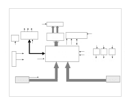
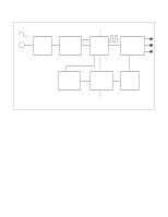
Block Diagram
 |
View all Dell 1800FP manuals
Add to My Manuals
Save this manual to your list of manuals |
Page 7 highlights
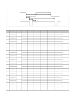
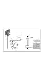
BLOCK DIAGRAM Power Board -7- Inverter CTL Power CTL Module CTL 12V LCD Module Inverter Micom 68HC08-BD48 H/V Sync 12V R,G,B differential LVDS (LVD S823) Out - CLK DE ,H/V Sync out R,G,B /Odd Memory (KM416S102BT) 3.3 VM M-CLK Address Data 48 Bit 5V 5V 5V 12V Gm5020 including AVD D3.3V 2.5V 3.3V Reg. Reg. 3.3V Reg. (ADC / TMDS Rx ) AVD D2.5V H/V-S ync 5V DVDD2.5V PVDD 3.3V DVDD 3.3V AVD D2.5V 3.3 VM AVD D 3.3V D-SUB H/V Sync R,G,B Digital Signal DVI-D
-
 1
1 -
 2
2 -
 3
3 -
 4
4 -
 5
5 -
 6
6 -
 7
7 -
 8
8 -
 9
9 -
 10
10 -
 11
11 -
 12
12 -
13
-
14
-
15
-
16
-
17
-
18
-
19
-
20
-
21
-
22
-
23
-
24
-
25
-
26
-
27
-
28
-
29
-
30
-
31
-
32
-
33
-
34
-
35
 |
 |

- 7 -
D-SUB
DVI-D
Gm5020
including
(ADC / TMDS Rx )
LVDS
(LVD S823)
Memory
(KM416S102BT)
H/V Sync
Micom
68HC08-BD48
M-CLK
Out - CLK
DE ,H/V Sync out
R,G,B /Odd
LCD Module
R,G,B
differential
Data 48 Bit
Address
Inverter CTL
Module CTL
R,G,B
Inverter
Digital Signal
3.3V
Reg.
DVDD 3.3V
AVD D 3.3V
12V
Power CTL
12V
2.5V
Reg.
DVDD2.5V
AVD D2.5V
3.3V
Reg.
PVDD 3.3V
3.3 VM
5V
5V
5V
H/V
Sync
H/V-S ync
3.3 VM
Power Board
12V
5V
AVD D3.3V
AVD D2.5V
BLOCK DIAGRAM