Dell 1800FP Service Manual - Page 8
Description Of Block Diagram - power
 |
View all Dell 1800FP manuals
Add to My Manuals
Save this manual to your list of manuals |
Page 8 highlights
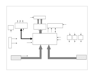
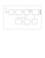
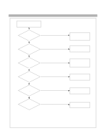
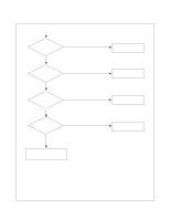
DESCRIPTION OF BLOCK DIAGRAM 1. Video Controller Part. This part amplifies the level of video signal for the digital conversion and converts from the analog video signal to the digital video signal using a pixel clock. The pixel clock for each mode is generated by the PLL. The range of the pixel clock is from 25MHz to 135MHz. This part consists of the Scaler and frame buffers which converts frame rate of input signal to 60Hz frame rate. The Scaler gets the video signal converted analog to digital, interpolates input to 1280 X 1024 resolution signal and outputs 8-bit R, G, B signal to transmitter. Especially pre-amp / ADC / Video controller are merged to one chip 'Gm5020' by Genesis. Also FRC is separate. 2. Display Data Transmitter Part. This part transmit digital signal from the Scaler to the receiver of module. 3. Power Part. This part consists of the one 5V, two 3.3V and one 2.5 regulators to convert power which is provided 12V, 5V in Power Board. 12V is provided for inverter, 5V is provided for Micom and LCD Panel. Also, 5V is converted 3.3V and 2.5V by regulator. Converted power is provided for IC in the main board. 4. MICOM Part. This part consists of EEPROM IC which stores control data, Reset IC and the Micom. The Micom distinguishes polarity and frequency of the H/V sync are supplied from signal cable. The controlled data of each modes is stored in EEPROM. 5. Inverter The inverter converts from DC12V to AC 700V and operate back-light lamp of module. -8-
-
 1
1 -
2
-
 3
3 -
 4
4 -
 5
5 -
 6
6 -
 7
7 -
 8
8 -
 9
9 -
 10
10 -
 11
11 -
 12
12 -
 13
13 -
14
-
15
-
16
-
17
-
18
-
19
-
20
-
21
-
22
-
23
-
24
-
25
-
26
-
27
-
28
-
29
-
30
-
31
-
32
-
33
-
34
-
35
 |
 |