Dell 2005FPW Service Manual - Page 9
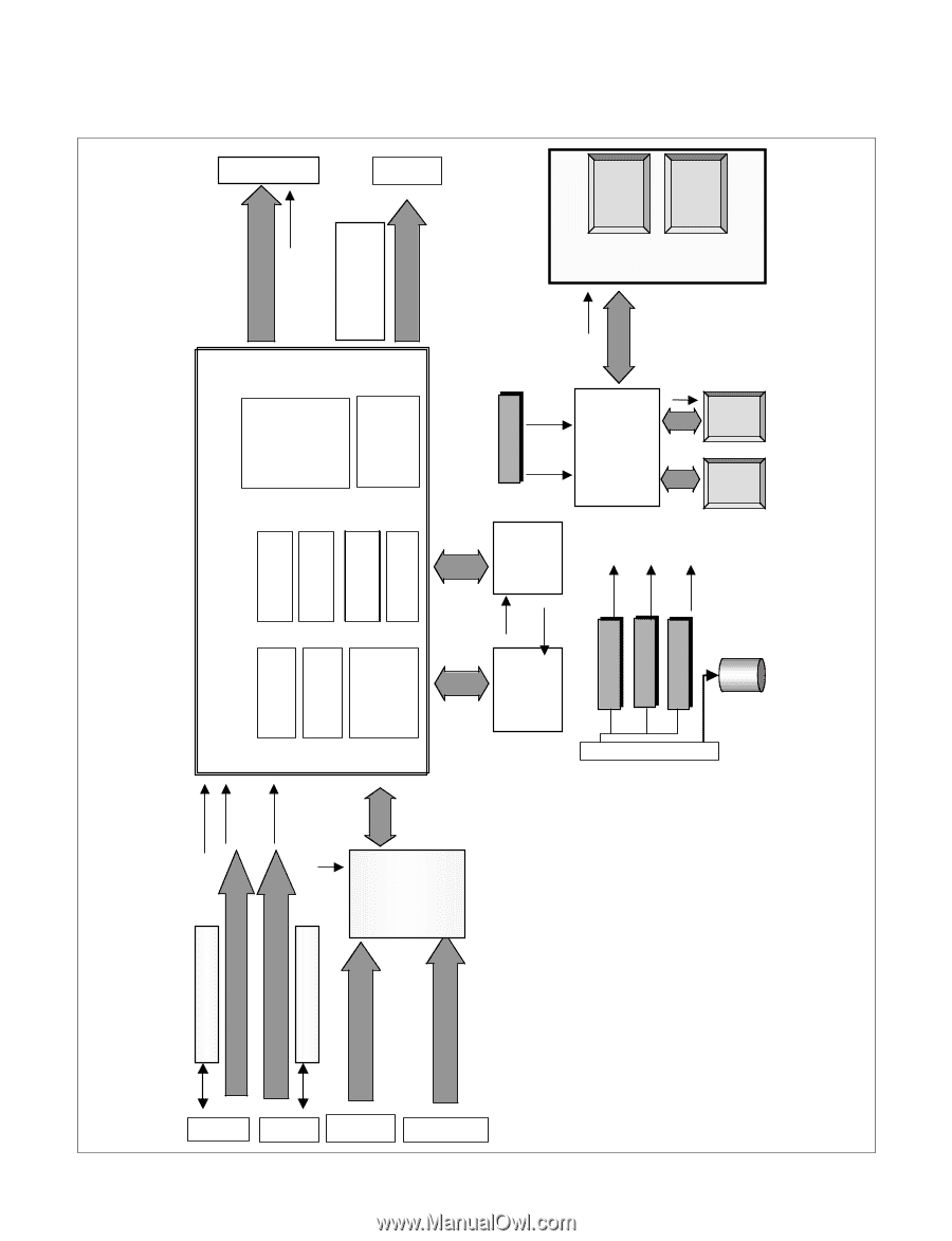
Block Diagram
 |
UPC - 012345698705
View all Dell 2005FPW manuals
Add to My Manuals
Save this manual to your list of manuals |
Page 9 highlights
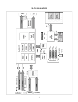
Composite S-video DVI-D D-Sub BLOCK DIAGRAM -9- EEPROM(EDID) 3.3V Analog I(R/G/B) 2.5V DVI(TMDS) 1.8V EEPROM(EDID) 3.3V YC+YU Decoder (TW9905) CVBS Gm1501 CF ADC PLL MICOM ROM DVI Rx Scaling OSD LVDS Tx Real colour Flash ROM Power 2.5V 3.3V DDR RAM Regulator 3.3V 1.8V 5V Regulator Regulator 3.3V 2.5V Regulator 1.8V 12V 12V Audio supply USB 2040H 5V Up stream Down Stream *2 LVDS 12V (LPL) 5V (AUO) EEPROM (System) 5V Down Stream Down Stream KEY Panel
-
 1
1 -
2
-
3
-
 4
4 -
 5
5 -
 6
6 -
 7
7 -
 8
8 -
 9
9 -
 10
10 -
 11
11 -
 12
12 -
 13
13 -
 14
14 -
15
-
16
-
17
-
18
-
19
-
20
-
21
-
22
-
23
-
24
-
25
-
26
-
27
-
28
-
29
-
30
-
31
-
32
-
33
 |
 |
- 9 -
Gm1501 CF
ADC
Scaling
PLL
OSD
LVDS
Analog I(R/G/B)
D-Sub
5V
Regulator
Regulator
3.3V
1.8V
12
5V
V
(AUO)
(LPL)
3.3V
2.5V
LVDS
Tx
DVI Rx
EEPROM(EDID)
EEPROM
(System)
DVI-D
DVI(TMDS)
KEY
1.8V
ROM
MICOM
Real
colour
Regulator
2.5V
Flash
ROM
DDR
RAM
2.5V
Panel
3.3V
S-video
EEPROM(EDID)
Composite
YC+YU
CVBS
Decoder
(TW9905)
3.3V
12V Audio
Power
supply
12V
Up
stream
Down
Stream
*2
USB
2040H
Down
Stream
Down
Stream
5V
Regulator
3.3V
1.8V
5V
BLOCK DIAGRAM