Dell 4210X Protocol Document - Page 2
Power On Command Send Low Byte Firstly - firmware
 |
UPC - 884116018049
View all Dell 4210X manuals
Add to My Manuals
Save this manual to your list of manuals |
Page 2 highlights
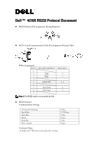
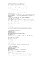
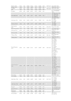
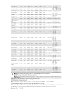
Control Command Syntax (From PC to Projector) [H][AC][SoP][CRC][ID][SoM][COMMAND] [H][AC][SoP][CRC][ID][SoM][COMMAND][Value] Example: Power On Command (Send Low Byte Firstly) Enter the following code: 0xbe, 0xef, 0x10, 0x05, 0x00, 0xc6, 0xff, 0x11, 0x11, 0x01, 0x00, 0x01 Header [H] ==> Fixed, "be (Low Byte), ef (High Byte)" Address Code [AC] ==> Fixed, "10" Size of Payload [SoP] ==> Byte size from MsgID to Command Code, "05 (Low Byte), 00 (High Byte)" or Byte size from MsgID to Value, "06 (Low Byte), 00 (High Byte)". CRC16 [CRC] ==> CRC value, "c6 (Low Byte), ff (High Byte)" MsgID [ID] ==> Fixed, "11 11" MsgSize [SoM] ==> Byte size of Command Code, "01 (Low Byte), 00 (High Byte)" or Byte size of Command Code and Value, "02 (Low Byte), 00 (High Byte)" Command Code [COMMAND] ==> "Power On" Command, "01" Projector Response Message Table Byte0 value: 0x00: Success 0x01: Invalid Command (on the control command list but no valid) 0x02: Error Command (includes CRC error and unknown commands) Projector Response System Status Byte0, Byte1, Byte2 Byte0: 0x00 (Success) Byte1: 0xff (the Command Code of System Status) Byte2: Return status Ex: When the projector is in standby mode, the return status will be 0x01. Projector Response Lamp Hour Byte0, Byte1, Byte2, Byte3 Byte0: 0x00 (Success) Byte1: 0x2f (the Command Code of Lamp Hour) Byte2: LSB (Hex) Byte3: MSB (Hex) Ex: 800 (3x256 + 2x16 = 800) hours --> 0x00, 0x2f, 0x20, 0x03 Firmware Version Response Byte0, Byte1, Byte2, Byte3...Byte7 Byte0: 0x00 (Success) Byte1: 0x30 (the Command Code of Firmware Version) Byte2...Byte7 Firmware version: 6 Bytes ASCII Code: "M0RXXX" XXX: 000-999 Ex: Version M0R001 Æ "M0R001" Æ0x4d, 0x30, 0x52, 0x30, 0x30, 0x31 (Success, the Command Code of FW Version, 6 Bytes ASCII Code: "M0RXXX")
-
 1
1 -
 2
2 -
 3
3 -
 4
4 -
 5
5
 |
 |
