Dell ALIENWARE AURORA Service Manual - Page 92
Replacing the Front Bezel
 |
UPC - 067540555575
View all Dell ALIENWARE AURORA manuals
Add to My Manuals
Save this manual to your list of manuals |
Page 92 highlights
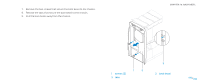
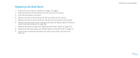
Replacing the Front Bezel 1. Follow the instructions in "Before You Begin" on page 6. 2. Align the front bezel with the front of the chassis. 3. Replace the three screws on the right side that secure the front bezel to the chassis. 4. Lay the chassis on its side. 5. Connect the front-bezel cables to the connectors on the master I/O board. 6. Replace the seven screws that secure the front bezel to the chassis. 7. Replace the right side-panel(s) (see "Replacing the Right Side-Panel(s)" on page 81). 8. Replace the drive-bay shroud (see "Replacing the Drive-Bay Shroud" on page 19). 9. Close the PCI shroud (see "Closing the PCI Shroud" on page 18). 10. Replace the left side-panel (see "Replacing the Left Side-Panel" on page 11). 11. Connect your computer and devices to electrical outlets and then turn them on. CHAPTER 18: FRONT BEZEL 092 /092
-
 1
1 -
2
-
3
-
4
-
5
-
6
-
7
-
8
-
9
-
10
-
11
-
12
-
13
-
14
-
15
-
16
-
17
-
18
-
19
-
20
-
21
-
22
-
23
-
24
-
25
-
26
-
27
-
28
-
29
-
30
-
31
-
32
-
33
-
34
-
35
-
36
-
37
-
38
-
39
-
40
-
41
-
42
-
43
-
44
-
45
-
46
-
47
-
48
-
49
-
50
-
51
-
52
-
53
-
54
-
55
-
56
-
57
-
58
-
59
-
60
-
61
-
62
-
63
-
64
-
65
-
66
-
67
-
68
-
69
-
70
-
71
-
72
-
73
-
74
-
75
-
76
-
77
-
78
-
79
-
80
-
81
-
82
-
83
-
84
-
85
-
86
-
 87
87 -
 88
88 -
 89
89 -
 90
90 -
 91
91 -
 92
92 -
 93
93 -
 94
94 -
 95
95 -
 96
96 -
 97
97 -
98
-
99
-
100
-
101
-
102
-
103
-
104
-
105
-
106
-
107
-
108
-
109
-
110
-
111
-
112
-
113
-
114
-
115
-
116
-
117
 |
 |
