Dell Alienware Area 51 R2 Service Manual
Dell Alienware Area 51 R2 Manual
 |
View all Dell Alienware Area 51 R2 manuals
Add to My Manuals
Save this manual to your list of manuals |
Dell Alienware Area 51 R2 manual content summary:
- Dell Alienware Area 51 R2 | Service Manual - Page 1
Alienware Area-51 Service Manual Computer Model: Alienware Area-51 R2 Regulatory Model: D03X Regulatory Type: D03X001 - Dell Alienware Area 51 R2 | Service Manual - Page 2
potential damage to hardware or loss of data and tells you how to avoid the problem. WARNING: A WARNING indicates a potential for property damage, personal injury, or death. Copyright © 2014 Dell Inc. All rights reserved. This product is protected by U.S. and international copyright and intellectual - Dell Alienware Area 51 R2 | Service Manual - Page 3
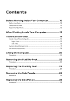
Contents Before Working Inside Your Computer 10 Before You Begin 10 Safety Instructions 10 Recommended Tools 12 After Working Inside Your Computer 13 Technical Overview 14 Inside View of Your Computer 14 Right View...15 Left View...16 System- - Dell Alienware Area 51 R2 | Service Manual - Page 4
29 Prerequisites...29 Procedure...30 Replacing the Battery 31 Procedure...31 Post-requisites 32 Removing the Battery Case 33 Prerequisites...33 Procedure...33 Replacing the Battery Case 36 Procedure...36 Post-requisites 36 Removing the Hard Drive 37 Prerequisites...37 Procedure...37 Replacing - Dell Alienware Area 51 R2 | Service Manual - Page 5
Removing the Right AlienFX Side-Panel Connector 45 Prerequisites...45 Procedure...45 Replacing the Right AlienFX Side-Panel Connector 48 Procedure...48 Post-requisites 48 Removing the Left AlienFX Side-Panel Connector 49 Prerequisites...49 Procedure...49 Replacing the Left AlienFX Side-Panel - Dell Alienware Area 51 R2 | Service Manual - Page 6
...62 Procedure...62 Replacing the Memory Module(s 64 Procedure...64 Post-requisites 65 Removing the Graphics Card 66 Prerequisites...66 Procedure...66 Replacing the Graphics Card 69 Procedure...69 Post-requisites 69 Removing the Multiple Graphics Cards 70 Prerequisites...70 Procedure...70 - Dell Alienware Area 51 R2 | Service Manual - Page 7
Replacing the Full-length Graphics Cards 79 Procedure...79 Post-requisites 79 Removing the PCI Fan 80 -sensor 88 Procedure...88 Post-requisites 88 Removing the Memory Fan 89 Prerequisites...89 Procedure...89 Replacing the Memory Fan 91 Procedure...91 Post-requisites 91 Removing the - Dell Alienware Area 51 R2 | Service Manual - Page 8
Procedure...101 Replacing the Power-Supply Unit 104 Procedure...105 Post-requisites 106 Removing the Coin-Cell Battery 107 Prerequisites...107 Procedure...107 Replacing the Coin-Cell Battery 109 Procedure...109 Post-requisites 109 Removing the Wireless Card 110 Prerequisites...110 Procedure - Dell Alienware Area 51 R2 | Service Manual - Page 9
Replacing the Wireless Card 112 Procedure...112 Post-requisites 112 Removing the Logo Board 113 Prerequisites...113 Procedure...113 Replacing the Logo Board 121 Entering System Setup 121 System Setup Options 121 Clearing Forgotten Passwords 130 Clearing CMOS Settings 131 Flashing the BIOS 132 - Dell Alienware Area 51 R2 | Service Manual - Page 10
your computer. - Windows 8.1: On the Start screen, click or tap the power icon → Shut down. - Windows 7: Click or card and optical disc from your computer, if applicable. 7 After the computer is unplugged, press and hold the power button for 5 seconds to ground the system board. Safety Instructions - Dell Alienware Area 51 R2 | Service Manual - Page 11
damaging the components and cards, handle them by their edges and avoid touching pins and contacts. CAUTION: Only a certified service technician is authorized to remove the computer cover and access any of the components inside the computer. See the safety instructions for complete information about - Dell Alienware Area 51 R2 | Service Manual - Page 12
CAUTION: Press and eject any installed card from the mediacard reader. Recommended Tools The procedures in this document may require the following tools: • Philips screwdriver • Flat-head screwdriver • Plastic scribe 12 - Dell Alienware Area 51 R2 | Service Manual - Page 13
screws remain inside your computer. 2 Connect any external devices, peripherals, and cables you removed before working on your computer. 3 Replace any media cards, discs, and any other part(s) that you removed before working on your computer. 4 Connect your computer and all attached devices to their - Dell Alienware Area 51 R2 | Service Manual - Page 14
the safety information that shipped with your computer and follow the steps in Before Working Inside Your Computer. After working inside your computer, follow the instructions in After Working Inside Your Computer. For more safety best practices, see the Regulatory Compliance home page at - Dell Alienware Area 51 R2 | Service Manual - Page 15
Right View 1 processor liquid-cooling assembly-fan 2 graphics card 3 system board 4 power-supply 5 AlienFX side-panel connector 6 PCI fan 7 processor liquid-cooling assembly 8 memory modules pump 9 memory fan (top fan) 15 - Dell Alienware Area 51 R2 | Service Manual - Page 16
Left View 1 optical drive (ODD) 3 drive-bay heat-sensor 5 AlienFX side-panel connector 7 3.5 inch drive bracket (HDD1) 9 3.5 inch drive bracket (HDD3) 2 I/O board (IO BRD) 4 2.5 inch drive bracket (HDD4/ HDD5) 6 rear I/O accessibility lighting batteries 8 3.5 inch drive bracket (HDD2) 16 - Dell Alienware Area 51 R2 | Service Manual - Page 17
System-Board Components 1 processor liquid cooling-assembly 2 audio connector (AUDIO101) fan (LCM_FAN1) 3 PCI-Express x16 slot (SLOT1) 4 low pin count debug header (LPC1) 5 password reset jumper (PASSWORD1) 6 PCI-Express x1 slot (SLOT2) 17 - Dell Alienware Area 51 R2 | Service Manual - Page 18
(SLOT3) 8 M.2 connector (wireless card) 9 coin-cell battery socket (BAT1) 10 CMOS reset jumper (CLEAR CMOS1) 11 memory fan connector (TOP_FAN1) 30 processor-power connector (CPU PWR1) 31 processor liquid-cooling assembly 32 memory-module slot (DIMM2) pump-fan connector (PUMP_FAN1) 33 memory - Dell Alienware Area 51 R2 | Service Manual - Page 19
(POGO_IN_L1) (POGO_IN_R1) 5 USB connector (USB1) 6 debug connector (DEBUG1) 7 front I/O control connector (FIO_PWR1) 8 front I/O connector (USB3_FIO1) 9 main-power connector (PWR1) 10 optical drive power connector (ODD1) 11 logo board connector (LOGO1) 12 audio connector (AUDIOIO1) 19 - Dell Alienware Area 51 R2 | Service Manual - Page 20
Lifting the Computer Procedure 1 With both hands, hold the handle on top of the computer. 20 - Dell Alienware Area 51 R2 | Service Manual - Page 21
2 Lift the computer. 1 handle 2 computer 21 - Dell Alienware Area 51 R2 | Service Manual - Page 22
Your Computer. After working inside your computer, follow the instructions in After Working Inside Your Computer. For more safety best practices, see the Regulatory Compliance home page at dell.com/regulatory_compliance. Procedure 1 Tilt the computer towards the front until - Dell Alienware Area 51 R2 | Service Manual - Page 23
3 Lift the stability foot off the computer. 1 stability foot 3 computer 2 screws (2) 23 - Dell Alienware Area 51 R2 | Service Manual - Page 24
4 Tilt the computer back to the upright position. 24 - Dell Alienware Area 51 R2 | Service Manual - Page 25
Your Computer. After working inside your computer, follow the instructions in After Working Inside Your Computer. For more safety best practices, see the Regulatory Compliance home page at dell.com/regulatory_compliance. Procedure 1 Tilt the computer towards the front until - Dell Alienware Area 51 R2 | Service Manual - Page 26
Your Computer. After working inside your computer, follow the instructions in After Working Inside Your Computer. For more safety best practices, see the Regulatory Compliance home page at dell.com/regulatory_compliance. Procedure NOTE: Make sure that you remove the security - Dell Alienware Area 51 R2 | Service Manual - Page 27
3 Pull and lift the right side-panel away from the chassis. 1 screw 2 security-cable slot latch 3 release panel 4 right side-panel 4 Repeat the procedure from step 2 to step 3 on the left side-panel. 27 - Dell Alienware Area 51 R2 | Service Manual - Page 28
Before Working Inside Your Computer. After working inside your computer, follow the instructions in After Working Inside Your Computer. For more safety best practices, see the Regulatory Compliance home page at dell.com/regulatory_compliance. Procedure 1 Align the tabs on the right side-panel with - Dell Alienware Area 51 R2 | Service Manual - Page 29
the safety information that shipped with your computer and follow the steps in Before Working Inside Your Computer. After working inside your computer, follow the instructions in After Working Inside Your Computer. For more safety best practices, see the Regulatory Compliance home page at - Dell Alienware Area 51 R2 | Service Manual - Page 30
Procedure Slide and open the battery-case door and remove the batteries from the battery-case. 1 battery-case door 2 AA batteries (2) 30 - Dell Alienware Area 51 R2 | Service Manual - Page 31
the safety information that shipped with your computer and follow the steps in Before Working Inside Your Computer. After working inside your computer, follow the instructions in After Working Inside Your Computer. For more safety best practices, see the Regulatory Compliance home page at - Dell Alienware Area 51 R2 | Service Manual - Page 32
1 battery-case door 2 AA batteries (2) Post-requisites Replace the right side-panel. See "Replacing the Side Panels". 32 - Dell Alienware Area 51 R2 | Service Manual - Page 33
Working Inside Your Computer. After working inside your computer, follow the instructions in After Working Inside Your Computer. For more safety best practices, see the Regulatory Compliance home page at dell.com/regulatory_compliance. Prerequisites 1 Remove the stability foot. 2 Remove the right - Dell Alienware Area 51 R2 | Service Manual - Page 34
3 Remove the batteries from the battery-compartment. 1 battery-case door 2 AA batteries (2) 4 Press the releasing clips on the cable connector to disconnect the batterycase cable from the chassis. 5 Remove the screws that secure the battery compartment to the chassis. 34 - Dell Alienware Area 51 R2 | Service Manual - Page 35
6 Lift the battery-case off the chassis. 1 battery-case cable 3 battery-case 2 battery-case connector 4 screws (2) 35 - Dell Alienware Area 51 R2 | Service Manual - Page 36
. After working inside your computer, follow the instructions in After Working Inside Your Computer. For more safety best practices, see the Regulatory Compliance home page at dell.com/regulatory_compliance. Procedure 1 Align the screw holes on the battery-case with the screw holes on the chassis - Dell Alienware Area 51 R2 | Service Manual - Page 37
inside your computer, follow the instructions in After Working Inside Your Computer. For see the Regulatory Compliance home page at dell.com/regulatory_compliance. CAUTION: Hard drives are chassis on the right side. 2 Disconnect the power cable and data cable from the hard drive. 3 Remove the - Dell Alienware Area 51 R2 | Service Manual - Page 38
4 Using the tab, slide and remove the hard-drive assembly from the chassis. 1 power cable 2 data cable 3 chassis 4 screw 5 hard-drive assembly 5 Remove the screws that secure the hard-drive bracket to the hard drive. 38 - Dell Alienware Area 51 R2 | Service Manual - Page 39
6 Slide and remove the hard drive from the hard-drive bracket. NOTE: Repeat step 2 to step 5 to remove any other hard drives installed in your computer. 1 screws (4) 3 hard-drive bracket 2 hard drive 39 - Dell Alienware Area 51 R2 | Service Manual - Page 40
your computer, follow the instructions in After Working Inside Your Computer. see the Regulatory Compliance home page at dell.com/regulatory_compliance. CAUTION: Hard drives secure the hard-drive assembly to the chassis. 5 Connect the power cable and data cable to the hard-drive. NOTE: Repeat step - Dell Alienware Area 51 R2 | Service Manual - Page 41
inside your computer, follow the instructions in After Working Inside Your Computer. see the Regulatory Compliance home page at dell.com/regulatory_compliance. Prerequisites 1 Remove the stability chassis on the right side. 2 Disconnect the power and data cable from the optical drive. 3 Remove the screw - Dell Alienware Area 51 R2 | Service Manual - Page 42
4 Slide and lift the optical-drive assembly of the chassis. 1 screw 2 optical-drive assembly 3 data cable and power cable 5 Remove the screws that secure the optical-drive bracket to the optical drive. 42 - Dell Alienware Area 51 R2 | Service Manual - Page 43
6 Slide and remove the optical drive from the optical-drive bracket. 1 screws (2) 3 optical-drive bracket 2 optical drive 43 - Dell Alienware Area 51 R2 | Service Manual - Page 44
inside your computer, follow the instructions in After Working Inside Your Computer. see the Regulatory Compliance home page at dell.com/regulatory_compliance. Procedure 1 Align the optical-drive bay assembly to the chassis. 5 Plug the power cable and data cable to the optical drive. Post-requisites - Dell Alienware Area 51 R2 | Service Manual - Page 45
Your Computer. After working inside your computer, follow the instructions in After Working Inside Your Computer. For more safety best practices , see the Regulatory Compliance home page at dell.com/regulatory_compliance. Prerequisites 1 Remove the stability foot. 2 Remove both - Dell Alienware Area 51 R2 | Service Manual - Page 46
4 Remove the right AlienFX side-panel connector assembly from the chassis. 1 screw 3 AlienFX side-panel cable 2 right AlienFX side-panel connector assembly 4 AlienFX side-panel connector 46 - Dell Alienware Area 51 R2 | Service Manual - Page 47
5 Remove the screws that secure the right AlienFX side-panel connector to the bracket and set it aside in a secure location. 1 screws (2) 2 right AlienFX side-panel connector 47 - Dell Alienware Area 51 R2 | Service Manual - Page 48
Your Computer. After working inside your computer, follow the instructions in After Working Inside Your Computer. For more safety best practices, see the Regulatory Compliance home page at dell.com/regulatory_compliance. Procedure 1 Replace the screws that secure the right - Dell Alienware Area 51 R2 | Service Manual - Page 49
Your Computer. After working inside your computer, follow the instructions in After Working Inside Your Computer. For more safety best practices , see the Regulatory Compliance home page at dell.com/regulatory_compliance. Prerequisites 1 Remove the stability foot. 2 Remove both - Dell Alienware Area 51 R2 | Service Manual - Page 50
2 Disconnect the cable that connects the left AlienFX side-panel connector to the I/O board. 1 AlienFX side-panel connector 3 I/O board 2 left AlienFX side-panel cable 3 Turn the chassis over. 4 Remove the AlienFX side-panel cable through the routing holes. 5 Remove the screw that secures the - Dell Alienware Area 51 R2 | Service Manual - Page 51
6 Remove the left AlienFX side-panel connector assembly from the chassis. 1 screw 2 left AlienFX side-panel connector assembly 51 - Dell Alienware Area 51 R2 | Service Manual - Page 52
7 Remove the screws that secure the AlienFX side-panel connector to the bracket and set it aside in a secure location. 1 screw 2 left AlienFX side-panel connector 52 - Dell Alienware Area 51 R2 | Service Manual - Page 53
Your Computer. After working inside your computer, follow the instructions in After Working Inside Your Computer. For more safety best practices, see the Regulatory Compliance home page at dell.com/regulatory_compliance. Procedure 1 Replace the screws that secure the left - Dell Alienware Area 51 R2 | Service Manual - Page 54
Your Computer. After working inside your computer, follow the instructions in After Working Inside Your Computer. For more safety best practices, see the Regulatory Compliance home page at dell.com/regulatory_compliance. Prerequisites 1 Remove the stability foot. 2 Remove the - Dell Alienware Area 51 R2 | Service Manual - Page 55
2 Disconnect all cables from the connectors on the I/O board. NOTE: Note the routing of all cables as you remove them so that you can reroute them correctly after you replace the I/O board. 1 cables 2 connector 3 I/O board 3 Remove the screws that secure the I/O board to the chassis. 55 - Dell Alienware Area 51 R2 | Service Manual - Page 56
4 Remove the I/O board out of the chassis. 1 I/O board 2 screws (2) 56 - Dell Alienware Area 51 R2 | Service Manual - Page 57
Before Working Inside Your Computer. After working inside your computer, follow the instructions in After Working Inside Your Computer. For more safety best practices, see the Regulatory Compliance home page at dell.com/regulatory_compliance. Procedure 1 Align the screw holes on the I/O board to the - Dell Alienware Area 51 R2 | Service Manual - Page 58
Your Computer. After working inside your computer, follow the instructions in After Working Inside Your Computer. For more safety best practices , see the Regulatory Compliance home page at dell.com/regulatory_compliance. Prerequisites 1 Remove the stability foot. 2 Remove both - Dell Alienware Area 51 R2 | Service Manual - Page 59
3 Disconnect the drive-bay heat-sensor cable from the connector on the system board. 1 drive-bay heat-sensor connector 2 drive-bay heat-sensor cable connector 3 drive-bay heat-sensor cable 4 Turn the chassis over. 5 Remove the cable through the sensor bracket. 6 Locate the drive-bay heat-sensor. - Dell Alienware Area 51 R2 | Service Manual - Page 60
9 Slide the drive-bay heat-sensor cable out of the sensor bracket. 1 release tab 3 drive-bay heat-sensor cable 2 securing clip 60 - Dell Alienware Area 51 R2 | Service Manual - Page 61
Your Computer. After working inside your computer, follow the instructions in After Working Inside Your Computer. For more safety best practices , see the Regulatory Compliance home page at dell.com/regulatory_compliance. Procedure 1 Reroute the drive-bay heat-sensor in the - Dell Alienware Area 51 R2 | Service Manual - Page 62
see the Regulatory Compliance home page at dell.com/regulatory_compliance. Prerequisites 1 Remove the stability foot. 2 Remove both the left and right side-panels. See "Removing the Side Panels". Procedure 1 Lay the computer on the left side. 2 Locate the memory modules on the system board. For more - Dell Alienware Area 51 R2 | Service Manual - Page 63
4 Grasp the memory module near the securing clip, and then gently ease the memory module out of the memory-module slot. NOTE: Repeat step 2 to step 3 to remove any other memory modules installed in your computer. 1 securing clips (2) 3 memory-module slot 2 memory module 63 - Dell Alienware Area 51 R2 | Service Manual - Page 64
the safety information that shipped with your computer and follow the steps in Before Working Inside Your Computer. After working inside your computer, follow the instructions in After Working Inside Your Computer. For more safety best practices, see the Regulatory Compliance home page at - Dell Alienware Area 51 R2 | Service Manual - Page 65
module snaps into position and the securing clips lock in place. NOTE: If you do not hear the click, remove the memory module and reinstall it. 1 memory module 3 notch 2 memory-module slot Post-requisites 1 Remove both the left and right side-panels. See "Removing the Side Panels". 2 Replace the - Dell Alienware Area 51 R2 | Service Manual - Page 66
Removing the Graphics Card WARNING: Before working inside your computer, read the safety information that shipped with your computer and follow the steps in Before Working Inside Your Computer. After working inside your computer, follow the instructions in After Working Inside Your Computer. For - Dell Alienware Area 51 R2 | Service Manual - Page 67
5 Press the releasing clips on the power-cable connectors to disconnect the power cables from the graphics card. NOTE: The location of the power supply connector varies depending on the video card installed. 1 screw cover 3 graphics card 2 screws (2) 4 power cables (2) 67 - Dell Alienware Area 51 R2 | Service Manual - Page 68
6 Press and hold the securing tab on the card connector, grasp the card by its top corners, and then ease the card out of the slot. 1 graphics card 2 releasing clips 68 - Dell Alienware Area 51 R2 | Service Manual - Page 69
is firmly seated. 3 Replace the screws that secure the graphics card to the chassis. 4 Connect the power cables to the graphics card. NOTE: The location of the power supply connector varies depending on the video card installed. 5 From outside the chassis, push the screw covers inside to cover the - Dell Alienware Area 51 R2 | Service Manual - Page 70
Removing the Multiple Graphics Cards WARNING: Before working inside your computer, read the safety information that shipped with your computer and follow the steps in Before Working Inside Your Computer. After working inside your computer, follow the instructions in After Working Inside Your - Dell Alienware Area 51 R2 | Service Manual - Page 71
3 Remove the graphics bridge that connects the graphics cards. 1 graphics bridge 4 Starting with the graphics card on the PCI-Express x16 card SLOT1, press and push the screw covers covering the screws that secure the graphics card. 5 Remove the screws that secure the graphics card to the chassis. - Dell Alienware Area 51 R2 | Service Manual - Page 72
6 Press the releasing clips on the power-cable connectors to disconnect the power cables from the graphics card. NOTE: The location of the power supply connector varies depending on the video card installed. 1 screw cover 3 power cables (2) 2 screws (2) 72 - Dell Alienware Area 51 R2 | Service Manual - Page 73
securing tab on the card connector, grasp the card by its top corners, and then ease the card out of the card connector. 1 graphics card 2 releasing clips 8 Repeat steps 2 to 5 to remove graphics card on the PCI-Express x16 card connector (SLOT3) and PCI-Express x16 card connector (SLOT5). 73 - Dell Alienware Area 51 R2 | Service Manual - Page 74
Replace the screws that secure the graphics card to the chassis. 5 Connect the graphics bridge that connects the graphics cards. 6 Connect the power cables to the graphics card. NOTE: The location of the power supply connector varies depending on the video card installed. 7 From outside the chassis - Dell Alienware Area 51 R2 | Service Manual - Page 75
Removing the Full-length Graphics Cards WARNING: Before working inside your computer, read the safety information that shipped with your computer and follow the steps in Before Working Inside Your Computer. After working inside your computer, follow the instructions in After Working Inside Your - Dell Alienware Area 51 R2 | Service Manual - Page 76
4 Pull the clamp away from the bracket. 1 clamp 2 bracket 5 Press and push the screw covers covering the screws that secure the graphics card. 6 Remove the screws that secure the graphics card to the chassis. 76 - Dell Alienware Area 51 R2 | Service Manual - Page 77
7 Press the releasing clips on the power-cable connectors to disconnect the power cables from the graphics card. NOTE: The location of the power supply connector varies depending on the video card installed. 1 screw cover 3 power cables (2) 2 screws (2) 77 - Dell Alienware Area 51 R2 | Service Manual - Page 78
8 Press and hold the securing tab on the card connector, grasp the card by its top corners, and then ease the card out of the card connector. 1 graphics card 2 releasing clips 78 - Dell Alienware Area 51 R2 | Service Manual - Page 79
clamp back into the bracket. 5 Replace the screws that secure the graphics card to the chassis. 6 Connect the power cables to the graphics card. NOTE: The location of the power supply connector varies depending on the video card installed. 7 From outside the chassis, push the screw covers inside to - Dell Alienware Area 51 R2 | Service Manual - Page 80
Your Computer. After working inside your computer, follow the instructions in After Working Inside Your Computer. For more safety best practices , see the Regulatory Compliance home page at dell.com/regulatory_compliance. Prerequisites 1 Remove the stability foot. 2 Remove both - Dell Alienware Area 51 R2 | Service Manual - Page 81
2 Remove the screws that secure the graphics-card bracket to the chassis. 1 screws (4) 2 graphics-card bracket 81 - Dell Alienware Area 51 R2 | Service Manual - Page 82
3 Remove the screws that secure the PCI fan to the chassis. 1 PCI fan 2 screws (2) 4 Disconnect the PCI-fan cable and front-bezel heat-sensor cable from the connector on the system board. 82 - Dell Alienware Area 51 R2 | Service Manual - Page 83
5 Pry out the PCI fan from the tabs securing it to the chassis. 1 tabs 3 PCI-fan cable 5 PCI-fan connector 2 PCI fan 4 front-bezel heat-sensor 6 Remove the screws securing the fan shroud to the PCI fan. 83 - Dell Alienware Area 51 R2 | Service Manual - Page 84
7 Pry out the PCI fan from the fan shroud by lifting the fan shroud upwards. 1 screws (4) 2 fan shroud 84 - Dell Alienware Area 51 R2 | Service Manual - Page 85
instructions in After Working Inside Your Computer. For more safety best practices, see the Regulatory Compliance home page at dell.com screw holes on the on the graphics-card bracket with the screw holes on the chassis. 7 Replace the screws that secure the graphics-card bracket to the chassis. Post - Dell Alienware Area 51 R2 | Service Manual - Page 86
Computer. After working inside your computer, follow the instructions in After Working Inside Your Computer. For more safety best practices, see the Regulatory Compliance home page at dell.com/regulatory_compliance. Prerequisites 1 Remove the stability foot. 2 Remove both the - Dell Alienware Area 51 R2 | Service Manual - Page 87
4 Slide the chassis heat-sensor cable out of the bracket. 1 chassis heat-sensor cable 3 release tab 2 securing clip 4 fan shroud 87 - Dell Alienware Area 51 R2 | Service Manual - Page 88
Your Computer. After working inside your computer, follow the instructions in After Working Inside Your Computer. For more safety best practices , see the Regulatory Compliance home page at dell.com/regulatory_compliance. Procedure 1 Reroute the chassis heat-sensor in the bracket - Dell Alienware Area 51 R2 | Service Manual - Page 89
see the Regulatory Compliance home page at dell.com/regulatory_compliance. Prerequisites 1 Remove the stability foot. 2 Remove both the left and right side-panels. See "Removing the Side Panels". Procedure 1 Lay the computer on the right side. 2 Disconnect the memory-fan cable from the connector on - Dell Alienware Area 51 R2 | Service Manual - Page 90
5 Lift the memory fan out of the chassis. 1 memory-fan 3 screw 2 release tab 4 memory-fan cable 90 - Dell Alienware Area 51 R2 | Service Manual - Page 91
in After Working Inside Your Computer. For more safety best practices, see the Regulatory Compliance home page at dell.com/regulatory_compliance. Procedure 1 Align the tabs on the memory fan with the slots on the chassis and slide the fan until it snaps into position. 2 Replace the screw - Dell Alienware Area 51 R2 | Service Manual - Page 92
your computer, follow the instructions in After Working Inside Your Computer. see the Regulatory Compliance home page at dell.com/regulatory_compliance. Prerequisites 1 Remove the for the processor, do not touch the heat transfer areas on the processor liquidcooling assembly. The oils in your skin - Dell Alienware Area 51 R2 | Service Manual - Page 93
5 Remove the screws that secure the processor liquid-cooling assembly fan to the chassis. 1 screws (4) 3 processor liquid-cooling assembly pump 5 processor liquid-cooling assembly fan cable 2 processor liquid-cooling assembly fan 4 processor liquid-cooling assembly pump cable 93 - Dell Alienware Area 51 R2 | Service Manual - Page 94
6 Slide and lift the processor liquid-cooling assembly out of the chassis. 1 processor liquid-cooling assembly 2 processor liquid-cooling assembly pump 94 - Dell Alienware Area 51 R2 | Service Manual - Page 95
Your Computer. After working inside your computer, follow the instructions in After Working Inside Your Computer. For more safety best practices, see the Regulatory Compliance home page at dell.com/regulatory_compliance. Procedure CAUTION: Incorrect alignment of the processor - Dell Alienware Area 51 R2 | Service Manual - Page 96
Post-requisites 1 Replace both the left and right side-panels. See "Removing the Side Panels". 2 Replace the stability foot. 96 - Dell Alienware Area 51 R2 | Service Manual - Page 97
Your Computer. After working inside your computer, follow the instructions in After Working Inside Your Computer. For more safety best practices , see the Regulatory Compliance home page at dell.com/regulatory_compliance. Prerequisites 1 Remove the stability foot. 2 Remove both - Dell Alienware Area 51 R2 | Service Manual - Page 98
5 Open the processor cover and gently lift the processor from the processor socket. 1 left release-lever 3 processor cover 2 right release-lever 4 processor 98 - Dell Alienware Area 51 R2 | Service Manual - Page 99
in Before Working Inside Your Computer. After working inside your computer, follow the instructions in After Working Inside Your Computer. For more safety best practices, see the Regulatory Compliance home page at dell.com/regulatory_compliance. CAUTION: If either the processor or the heat sink is - Dell Alienware Area 51 R2 | Service Manual - Page 100
5 Press down and push the right-release lever. Place it under the tab on the processor cover. 1 processor 3 processor cover 5 right release-lever 2 processor pin-1 connector 4 left release-lever Post-requisites 1 Replace the processor liquid-cooling assembly fan. 2 Replace both the left and - Dell Alienware Area 51 R2 | Service Manual - Page 101
panels. See "Removing the Side Panels". 3 Remove multiple graphics cards. 4 Remove the full length graphics cards. Procedure NOTE: Note the routing of all cables as you remove them so that you can reroute them correctly after you replace the power supply. 1 Lay the computer on the left side. 2 Press - Dell Alienware Area 51 R2 | Service Manual - Page 102
3 Remove the screws that secure the power-supply unit to the back of the chassis. 1 power cable 3 screws (4) 2 power supply 102 - Dell Alienware Area 51 R2 | Service Manual - Page 103
4 Lift the power-supply cover away from the chassis. 1 power supply 2 power-supply cover 5 Slide the power-supply unit out through the back of the chassis and remove it from the computer. 1 chassis 2 power-supply unit 103 - Dell Alienware Area 51 R2 | Service Manual - Page 104
Replacing the Power-Supply Unit WARNING: Before working inside your computer, read the safety information that shipped with your computer and follow the steps in Before Working Inside Your Computer. After working inside your computer, follow the instructions in After Working Inside Your Computer. - Dell Alienware Area 51 R2 | Service Manual - Page 105
hold the securing tab on the chassis and slide the power-supply unit into the chassis until it snaps into position. 1 securing tab 2 power supply unit 2 Align the notch on the power-supply cover with the tab on the chassis. 3 Slide the power-supply cover towards the tabs until it locks in place - Dell Alienware Area 51 R2 | Service Manual - Page 106
Post-requisites 1 Replace the full length graphics cards. 2 Replace the graphics card. 3 Replace both the left and right side-panels. See "Removing the Side Panels". 4 Replace the stability foot. 106 - Dell Alienware Area 51 R2 | Service Manual - Page 107
the BIOS settings before removing the coin-cell battery. Prerequisites 1 Remove the stability foot. 2 Remove both the left and right side-panels. See "Removing the Side Panels". 3 If you have multiple graphics cards installed, remove the graphics card. See "Removing the Graphics Card". Procedure - Dell Alienware Area 51 R2 | Service Manual - Page 108
2 Press the battery-release lever to remove the battery. 1 battery-release lever 2 coin-cell battery 108 - Dell Alienware Area 51 R2 | Service Manual - Page 109
instructions in After dell.com/regulatory_compliance. Procedure Insert the battery into the socket with the side labeled + facing up and press down the battery in the socket. Post-requisites 1 If you have multiple graphics cards installed, replace the graphics cards. See "Replacing the Graphics Card - Dell Alienware Area 51 R2 | Service Manual - Page 110
at dell.com/regulatory_compliance. Prerequisites 1 Remove the stability foot. See "Removing the Stability Foot". 2 Remove both the left and right side-panels. See "Removing the Side Panels". 3 If you have multiple graphics cards installed, remove the graphics card. See "Removing the Graphics Card - Dell Alienware Area 51 R2 | Service Manual - Page 111
4 Slide and pull the wireless card away from the wireless-card slot. 1 antenna cables 3 antenna cables connector 5 wireless-card slot 2 screw 4 wireless card 111 - Dell Alienware Area 51 R2 | Service Manual - Page 112
scheme for the wireless card supported by your computer. Connectors on the wireless card Antenna-cable sticker color Auxiliary (1) Black Main (2) White Post-requisites 1 If you have multiple graphics cards, replace the graphics card. See "Replacing the Graphics Card". 2 Replace both the left - Dell Alienware Area 51 R2 | Service Manual - Page 113
more safety best practices, see the Regulatory Compliance home page at dell.com/regulatory_compliance. Prerequisites 1 Remove the stability foot. 2 Remove both the left and right side-panels. See "Removing the Side Panels". 3 Remove the memory fan. Procedure NOTE: Note the routing of all cables as - Dell Alienware Area 51 R2 | Service Manual - Page 114
4 Slide the logo board out of the chassis. 1 logo board 2 connector 3 screw 5 Remove the screws that secure the logo board to the bracket. 114 - Dell Alienware Area 51 R2 | Service Manual - Page 115
6 Lift the logo board out of the bracket. 1 screws (6) 3 logo board 2 logo board bracket 115 - Dell Alienware Area 51 R2 | Service Manual - Page 116
in Before Working Inside Your Computer. After working inside your computer, follow the instructions in After Working Inside Your Computer. For more safety best practices, see the Regulatory Compliance home page at dell.com/regulatory_compliance. Procedure 1 Align the screw holes on the logo board to - Dell Alienware Area 51 R2 | Service Manual - Page 117
, follow the instructions in After Working Inside Your Computer. For more safety best practices, see the Regulatory Compliance home page at dell.com/regulatory_compliance. NOTE: Your computer's Service Tag is stored in the system board. You must enter the Service Tag in the BIOS setup program after - Dell Alienware Area 51 R2 | Service Manual - Page 118
Procedure NOTE: Note the routing of all cables as you remove them so that you can reroute them correctly after you replace the system board. For information on system board connectors, see "System-Board Components". 1 Lay the computer on the left side. 2 Disconnect all the cables connected to the - Dell Alienware Area 51 R2 | Service Manual - Page 119
, follow the instructions in After Working Inside Your Computer. For more safety best practices, see the Regulatory Compliance home page at dell.com/regulatory_compliance. NOTE: Your computer's Service Tag is stored in the system board. You must enter the Service Tag in the BIOS setup program after - Dell Alienware Area 51 R2 | Service Manual - Page 120
7 Replace the memory fan. 8 Replace the wireless card. 9 Replace both the left and right side-panels. See "Replacing the Side Panels". 10 Replace the stability foot. 120 - Dell Alienware Area 51 R2 | Service Manual - Page 121
installed in your computer, such as the amount of RAM, the size of the hard drive, and so on or restart) your computer. 2 During POST, when the DELL logo is displayed, watch for the F2 prompt to continue to wait until you see the operating system's desktop. Then, turn off your computer and try again - Dell Alienware Area 51 R2 | Service Manual - Page 122
Memory Technology Memory Speed CPU Information Processor Type Processor ID 122 Displays the current date in mm/dd/yyyy format. Displays the current time in hh:mm:ss format. Displays the BIOS version number. Displays the BIOS release date. Displays the product name. Default: Alienware Area-51 R2 - Dell Alienware Area 51 R2 | Service Manual - Page 123
Advanced Advanced BIOS Features OptionRom Display Screen CPU Configuration Hyper-Threading Technology XD Bit Capability Displays the CPU speed. Displays 6 drive installed in the computer. Allows you to display or hide the RAID Option ROM screen during POST. Default: Display. Allows you to enable or - Dell Alienware Area 51 R2 | Service Manual - Page 124
Advanced Intel(R) SpeedStep Technology CPU C states Active Processor Cores Integrated Devices USB Controller HD Audio Onboard LAN Controller Pxe Option Launch PXE OpROM UEFI PXE Driver PCIE GEN3 Power Management Setup AC Recovery Allows you to enable or disable Intel (R) Speedstep Technology. - Dell Alienware Area 51 R2 | Service Manual - Page 125
Deep Sleep is enabled. Default: Enabled in S5 Only. Chipset Spread Spectrum CPU Base Clock (MHz) Adjust CPU Base Clock Strap Ring Ratio DRAM Frequency DRAM Timing Mode CPU Ratio CPU Ratio Mode Overvoltage Configuration Memory voltage (24h OUT1) Memory voltage (26h OUT1) DMI and Uncore voltage (2Ah - Dell Alienware Area 51 R2 | Service Manual - Page 126
Delay (editable in Manual Mode). Displays the Four Activate Window (editable in Manual Mode). Displays the Write CAS Latency (editable in Manual Mode). Displays the Minimum CKE High and Low Pulse Width (editable in Manual Mode). Allows you to access the CPU Power Management Configuration submenu. - Dell Alienware Area 51 R2 | Service Manual - Page 127
Chipset Turbo Mode Long duration power limit Long duration maintained Short duration power limit 1-Core Ratio Limit 2-Core Ratio Limit 3-Core Ratio Limit 4-Core Ratio Limit 5-Core Ratio Limit 6-Core Ratio Limit 7-Core Ratio Limit 8-Core Ratio Limit VID override for Max Turbo Ratio CPU Current Limit - Dell Alienware Area 51 R2 | Service Manual - Page 128
Chipset Mailbox Configuration SVID Communication VCCIN Voltage CPU Core/Ring Voltage Mode CPU Core Voltage CPU Core Voltage Offset Mode CPU Core Voltage Offset CPU Ring Voltage CPU Ring Voltage Offset Mode CPU Ring Voltage Offset CPU SA Voltage Mode CPU SA Voltage CPU SA Voltage Offset Mode CPU SA - Dell Alienware Area 51 R2 | Service Manual - Page 129
Chipset Load Level 1 OC Settings Load Level 2 OC Settings Security Supervisor Password User Password Set Supervisor Password Boot Boot Configuration Bootup Numlock State Wait for 'F1' If Error Secure Boot Control Load Legacy OPROM Set Boot Priority Boot Mode USB Boot Support Allows you to select OC - Dell Alienware Area 51 R2 | Service Manual - Page 130
device. Default: Network. Sets the hard drive boot priority. The items displayed are dynamically updated according to the hard drives detected. Sets the USB storage drive boot priority. Sets the practices information, see the Regulatory Compliance Homepage at dell.com/regulatory_compliance. 130 - Dell Alienware Area 51 R2 | Service Manual - Page 131
Your Computer. After working inside your computer, follow the instructions in After Working Inside Your Computer. For more safety best practices, see the Regulatory Compliance home page at dell.com/regulatory_compliance. 1 Lay the system on the right side. 2 Remove - Dell Alienware Area 51 R2 | Service Manual - Page 132
foot. Flashing the BIOS You may need to flash (update) the BIOS when an update is available or when you replace the system board. To flash the BIOS: 1 Turn on the computer. 2 Go to dell.com/support. 3 If you have your computer's Service Tag, type your computer's Service Tag and click Submit - Dell Alienware Area 51 R2 | Service Manual - Page 133
version of the BIOS for your computer. 9 On the next page, select Single-file download and click Continue. 10 Save the file and once the download is complete, navigate to the folder where you saved the BIOS update file. 11 Double-click the BIOS update file icon and follow the instructions on the
-
 1
1 -
 2
2 -
 3
3 -
 4
4 -
 5
5 -
 6
6 -
 7
7 -
8
-
9
-
10
-
11
-
12
-
13
-
14
-
15
-
16
-
17
-
18
-
19
-
20
-
21
-
22
-
23
-
24
-
25
-
26
-
27
-
28
-
29
-
30
-
31
-
32
-
33
-
34
-
35
-
36
-
37
-
38
-
39
-
40
-
41
-
42
-
43
-
44
-
45
-
46
-
47
-
48
-
49
-
50
-
51
-
52
-
53
-
54
-
55
-
56
-
57
-
58
-
59
-
60
-
61
-
62
-
63
-
64
-
65
-
66
-
67
-
68
-
69
-
70
-
71
-
72
-
73
-
74
-
75
-
76
-
77
-
78
-
79
-
80
-
81
-
82
-
83
-
84
-
85
-
86
-
87
-
88
-
89
-
90
-
91
-
92
-
93
-
94
-
95
-
96
-
97
-
98
-
99
-
100
-
101
-
102
-
103
-
104
-
105
-
106
-
107
-
108
-
109
-
110
-
111
-
112
-
113
-
114
-
115
-
116
-
117
-
118
-
119
-
120
-
121
-
122
-
123
-
124
-
125
-
126
-
127
-
128
-
129
-
130
-
131
-
132
-
133
 |
 |

Alienware Area-51
Service Manual
Computer Model: Alienware Area-51 R2
Regulatory Model: D03X
Regulatory Type: D03X001