Dell Alienware Area-51 R4 Alienware Area-51 R5 Service Manual - Page 87
Replacing the handle bars, Procedure, Post-requisites, After working inside your computer
 |
View all Dell Alienware Area-51 R4 manuals
Add to My Manuals
Save this manual to your list of manuals |
Page 87 highlights
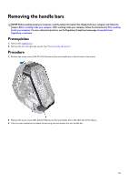
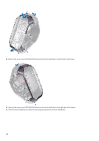
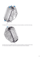
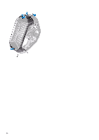
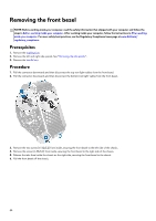
Replacing the handle bars NOTE: Before working inside your computer, read the safety information that shipped with your computer and follow the steps in Before working inside your computer. After working inside your computer, follow the instructions in After working inside your computer. For more safety best practices, see the Regulatory Compliance home page at www.dell.com/ regulatory_compliance. Procedure 1. Align and place the bottom-handle bar on the slot and snap the bottom-handle bar to the chassis. 2. Replace the seven screws (#6-32x6.5) that secure the bottom-handle bar to the left side of the chassis. 3. Replace the seven screws (#6-32x6.5) that secure the bottom-handle bar to the right side of the chassis. 4. Align and place the front-handle bar on the slot and snap the front-handle bar to the chassis. 5. Replace the seven screws (#6-32x6.5) that secure the front-handle bar to the left side of the chassis. 6. Replace the seven screws (#6-32x6.5) that secure the front-handle bar to the right side of the chassis. 7. Align and place the rear-handle bar on the slot and snap the rear-handle bar to the chassis. 8. Replace the seven screws (#6-32x6.5) that secure the rear-handle bar to the left side of the chassis. 9. Replace the seven screws (#6-32x6.5) that secure the rear-handle bar to the right side of the chassis. Post-requisites 1. Replace the left and right side-panels. See "Replacing the side panels". 2. Replace the stability foot. 87
-
 1
1 -
2
-
3
-
4
-
5
-
6
-
7
-
8
-
9
-
10
-
11
-
12
-
13
-
14
-
15
-
16
-
17
-
18
-
19
-
20
-
21
-
22
-
23
-
24
-
25
-
26
-
27
-
28
-
29
-
30
-
31
-
32
-
33
-
34
-
35
-
36
-
37
-
38
-
39
-
40
-
41
-
42
-
43
-
44
-
45
-
46
-
47
-
48
-
49
-
50
-
51
-
52
-
53
-
54
-
55
-
56
-
57
-
58
-
59
-
60
-
61
-
62
-
63
-
64
-
65
-
66
-
67
-
68
-
69
-
70
-
71
-
72
-
73
-
74
-
75
-
76
-
77
-
78
-
79
-
80
-
81
-
 82
82 -
 83
83 -
 84
84 -
 85
85 -
 86
86 -
 87
87 -
 88
88 -
 89
89 -
 90
90 -
 91
91 -
 92
92 -
93
-
94
-
95
-
96
-
97
-
98
-
99
-
100
-
101
-
102
-
103
-
104
-
105
-
106
-
107
-
108
-
109
-
110
-
111
-
112
-
113
-
114
-
115
-
116
-
117
-
118
-
119
-
120
-
121
 |
 |