Dell Alienware Aurora R15 Service Manual - Page 52
Processor liquid-cooling assembly
 |
View all Dell Alienware Aurora R15 manuals
Add to My Manuals
Save this manual to your list of manuals |
Page 52 highlights
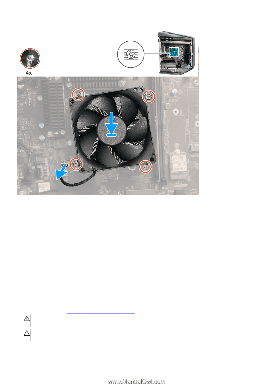
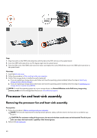
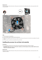
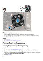
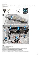
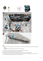
Steps 1. Place the processor fan and heat-sink assembly on the processor. 2. Align the captive screws on the processor fan heat-sink assembly with the screw holes on the system board. 3. In sequential order, tighten the four captive screws that secure the processor fan and heat-sink assembly to the system board. 4. Connect the processor-fan cable to the system board. Next steps 1. Install the left-side cover. 2. Follow the procedure in After working inside your computer. Processor liquid-cooling assembly Removing the processor liquid-cooling assembly Prerequisites 1. Follow the procedure in Before working inside your computer. WARNING: Despite having a plastic shield, the processor liquid-cooling assembly may be very hot during normal operation. Ensure that it had sufficient time to cool before you touch it. CAUTION: For maximum cooling of the processor, do not touch the heat transfer areas on the heat sink. The oils in your skin can reduce the heat transfer capability of the thermal grease. 2. Remove the left-side cover. 52
-
 1
1 -
2
-
3
-
4
-
5
-
6
-
7
-
8
-
9
-
10
-
11
-
12
-
13
-
14
-
15
-
16
-
17
-
18
-
19
-
20
-
21
-
22
-
23
-
24
-
25
-
26
-
27
-
28
-
29
-
30
-
31
-
32
-
33
-
34
-
35
-
36
-
37
-
38
-
39
-
40
-
41
-
42
-
43
-
44
-
45
-
46
-
 47
47 -
 48
48 -
 49
49 -
 50
50 -
 51
51 -
 52
52 -
 53
53 -
 54
54 -
 55
55 -
 56
56 -
 57
57 -
58
-
59
-
60
-
61
-
62
-
63
-
64
-
65
-
66
-
67
-
68
-
69
-
70
-
71
-
72
-
73
-
74
-
75
-
76
-
77
-
78
-
79
-
80
-
81
-
82
-
83
-
84
-
85
-
86
-
87
-
88
-
89
-
90
-
91
-
92
-
93
-
94
-
95
-
96
-
97
-
98
-
99
-
100
-
101
-
102
 |
 |