Dell Alienware Aurora R15 Service Manual - Page 80
SATA power connector SATA PWR, Side-light connector SIDE LIGHT
 |
View all Dell Alienware Aurora R15 manuals
Add to My Manuals
Save this manual to your list of manuals |
Page 80 highlights
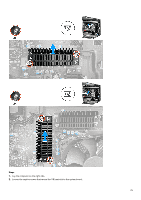
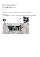
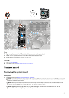
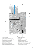
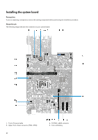
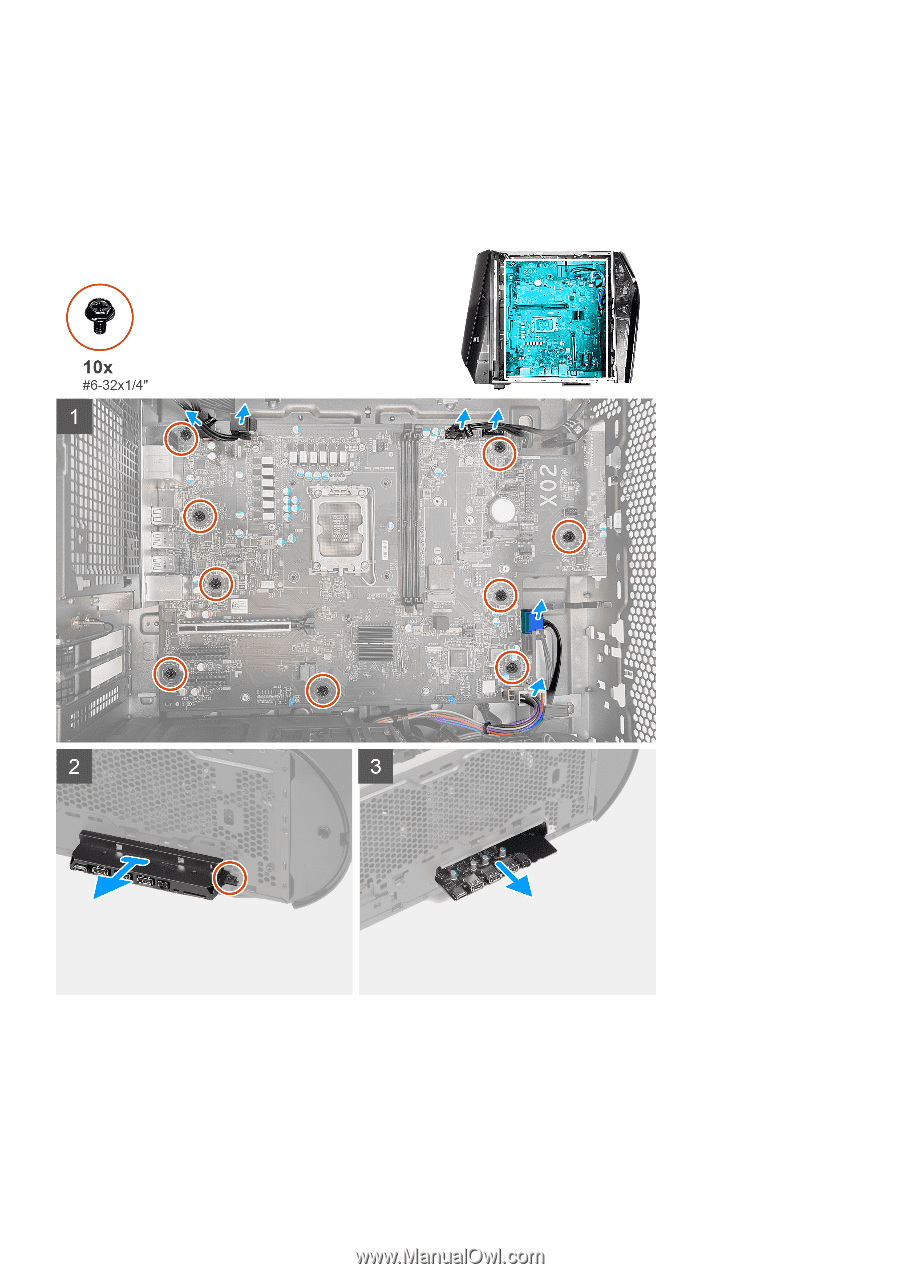
21. Power-supply connector (ATX3) 23. Power-supply connector (ATX2) 25.Top-chassis fan connector two (FAN_SYS5) 27. Memory-module slot, DIMM2 29.Side-light connector (SIDE LIGHT) 22. Top-chassis fan connector one (FAN_SYS4) 24.CPU socket 26.Memory-module slot, DIMM1 28. SATA power connector (SATA PWR) The following images indicate the location of the system board and provide a visual representation of the removal procedure. 80
-
 1
1 -
2
-
3
-
4
-
5
-
6
-
7
-
8
-
9
-
10
-
11
-
12
-
13
-
14
-
15
-
16
-
17
-
18
-
19
-
20
-
21
-
22
-
23
-
24
-
25
-
26
-
27
-
28
-
29
-
30
-
31
-
32
-
33
-
34
-
35
-
36
-
37
-
38
-
39
-
40
-
41
-
42
-
43
-
44
-
45
-
46
-
47
-
48
-
49
-
50
-
51
-
52
-
53
-
54
-
55
-
56
-
57
-
58
-
59
-
60
-
61
-
62
-
63
-
64
-
65
-
66
-
67
-
68
-
69
-
70
-
71
-
72
-
73
-
74
-
 75
75 -
 76
76 -
 77
77 -
 78
78 -
 79
79 -
 80
80 -
 81
81 -
 82
82 -
 83
83 -
 84
84 -
 85
85 -
86
-
87
-
88
-
89
-
90
-
91
-
92
-
93
-
94
-
95
-
96
-
97
-
98
-
99
-
100
-
101
-
102
 |
 |
21. Power-supply connector (ATX3)
22.Top-chassis fan connector one (FAN_SYS4)
23. Power-supply connector (ATX2)
24.CPU socket
25.Top-chassis fan connector two (FAN_SYS5)
26.Memory-module slot, DIMM1
27. Memory-module slot, DIMM2
28. SATA power connector (SATA PWR)
29.Side-light connector (SIDE LIGHT)
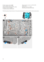
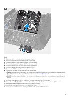
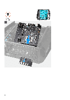
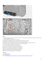
The following images indicate the location of the system board and provide a visual representation of the removal procedure.
80