Dell Alienware Aurora Ryzen Edition R10 Alienware Aurora Ryzen Edition Service - Page 11
Screw list, Table 1. Screw list
 |
View all Dell Alienware Aurora Ryzen Edition R10 manuals
Add to My Manuals
Save this manual to your list of manuals |
Page 11 highlights
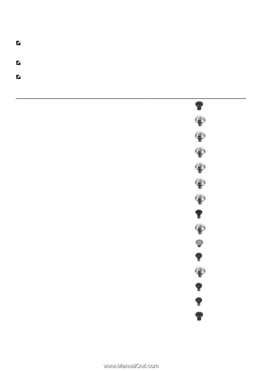
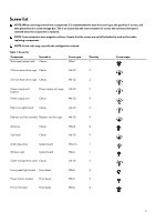
Screw list NOTE: When removing screws from a component, it is recommended to note the screw type, the quantity of screws, and then place them in a screw storage box. This is to ensure that the correct number of screws and correct screw type is restored when the component is replaced. NOTE: Some computers have magnetic surfaces. Ensure that the screws are not left attached to such surface when replacing a component. NOTE: Screw color may vary with the configuration ordered. Table 1. Screw list Component Side-panel release latch Secured to Chassis Screw type M3x4 Quantity 1 Screw image 2.5-inch hard-drive cage Chassis #6-32 2 3.5-inch hard-drive cage Chassis #6-32 2 Power-supply unit Power-supply unit cage #6-32 2 bracket Power-supply unit Chassis #6-32 4 Right tron-light board Chassis #6-32 4 Radiator and fan assembly Radiator and fan cage #6-32 4 Antennas Top bezel Chassis Chassis M3x4t 4 #6-32 4 Solid-state drive Wireless card System board System board Cable-management panel Chassis M2x2.5 1 M2x4 1 #6-32 2 Front-panel light-board Front bezel Power button module Front bezel Front I/O-panel Front bezel M2x4 4 M2x4 2 M3x4 4 11
-
 1
1 -
2
-
3
-
4
-
5
-
 6
6 -
 7
7 -
 8
8 -
 9
9 -
 10
10 -
 11
11 -
 12
12 -
 13
13 -
 14
14 -
 15
15 -
 16
16 -
17
-
18
-
19
-
20
-
21
-
22
-
23
-
24
-
25
-
26
-
27
-
28
-
29
-
30
-
31
-
32
-
33
-
34
-
35
-
36
-
37
-
38
-
39
-
40
-
41
-
42
-
43
-
44
-
45
-
46
-
47
-
48
-
49
-
50
-
51
-
52
-
53
-
54
-
55
-
56
-
57
-
58
-
59
-
60
-
61
-
62
-
63
-
64
-
65
-
66
-
67
-
68
-
69
-
70
-
71
-
72
-
73
-
74
-
75
-
76
-
77
-
78
-
79
-
80
-
81
-
82
-
83
-
84
-
85
-
86
-
87
-
88
-
89
-
90
-
91
-
92
-
93
-
94
-
95
-
96
-
97
-
98
-
99
-
100
-
101
-
102
-
103
 |
 |