Dell Alienware x15 R2 Service Manual - Page 58
Installing the I/O board, Power button, Removing the power button
 |
View all Dell Alienware x15 R2 manuals
Add to My Manuals
Save this manual to your list of manuals |
Page 58 highlights
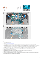
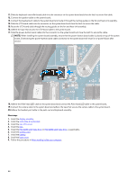
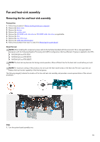
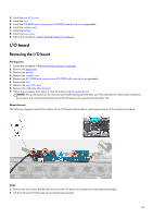
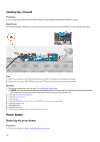
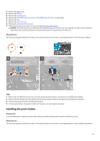
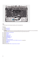
Installing the I/O board Prerequisites If you are replacing a component, remove the existing component before performing the installation process. About this task The following image(s) indicate the location of the I/O board and provides a visual representation of the installation procedure. Steps 1. Align the screw holes on the I/O board with the screw holes on the palm-rest and keyboard assembly. 2. Replace the four screws (M1.6x1.8) that secure the I/O board to the palm-rest and keyboard assembly. Next steps 1. Follow the procedure from step 3 to step 20 in Installing the system board. NOTE: The system board can be removed and installed along with the heat sink. This simplifies the removal and installation procedure and avoids breaking the thermal bond between the system board and heat sink. 2. Install the solid-state drive bracket. 3. Install the rear I/O-cover. 4. Install the fans. 5. Install the M.2 2230 solid-state drive or M.2 2280 solid-state drive, as applicable. 6. Install the wireless card. 7. Install the battery. 8. Install the base cover. 9. Follow the procedure in After working inside your computer. Power button Removing the power button Prerequisites 1. Follow the procedure in Before working inside your computer. 58
-
 1
1 -
2
-
3
-
4
-
5
-
6
-
7
-
8
-
9
-
10
-
11
-
12
-
13
-
14
-
15
-
16
-
17
-
18
-
19
-
20
-
21
-
22
-
23
-
24
-
25
-
26
-
27
-
28
-
29
-
30
-
31
-
32
-
33
-
34
-
35
-
36
-
37
-
38
-
39
-
40
-
41
-
42
-
43
-
44
-
45
-
46
-
47
-
48
-
49
-
50
-
51
-
52
-
 53
53 -
 54
54 -
 55
55 -
 56
56 -
 57
57 -
 58
58 -
 59
59 -
 60
60 -
 61
61 -
 62
62 -
 63
63 -
64
-
65
-
66
-
67
-
68
-
69
-
70
-
71
-
72
-
73
-
74
-
75
 |
 |
