Dell Brocade 300 Hardware Reference Manual
Dell Brocade 300 Manual
 |
View all Dell Brocade 300 manuals
Add to My Manuals
Save this manual to your list of manuals |
Dell Brocade 300 manual content summary:
- Dell Brocade 300 | Hardware Reference Manual - Page 1
Publication Number: 53-1000424-03 Publication Date: March, 2008 Brocade 5000 Hardware Reference Manual Supporting Fabric OS v5.3 Supporting Brocade 5000 - Dell Brocade 300 | Hardware Reference Manual - Page 2
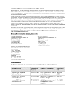
Reference Manual Brocade 5000 Hardware Reference Manual Publication Number Summary of Changes Publication Date 53-1000424-01 None; this is the first draft of December a new document. 2006 53-1000424-02 Rebranded and updated with June 2007 technical changes. 53-1000424-03 Added Japanese power - Dell Brocade 300 | Hardware Reference Manual - Page 3
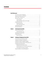
6 Setting Up the Brocade 5000 as a Standalone Unit 7 Configuring the Brocade 5000 7 Setting the Switch Date and Time 12 Synchronizing Local Time with an External Source 12 Correcting the Time Zone of a Switch 13 Recommendations for Cable Management 13 Brocade 5000 Hardware Reference Manual - Dell Brocade 300 | Hardware Reference Manual - Page 4
Switch Components 23 Weight and Physical Dimensions 24 Facility Requirements 24 Power Supply Specifications 25 Power Cords (Japan, Denan 25 Environmental Requirements 26 General Specifications 26 Data Transmission Ranges 27 Memory Specifications 28 Fibre Channel Port Specifications - Dell Brocade 300 | Hardware Reference Manual - Page 5
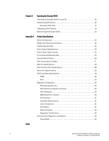
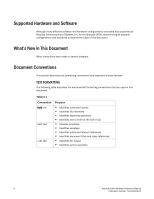
a complete set of Brocade 5000 switch installation procedures and an overview of the switch hardware. This document is specific to the Brocade 5000 switch running Fabric OS v5.2.1. "About This Document" contains the following sections: • "How This Document Is Organized," next • "Supported Hardware - Dell Brocade 300 | Hardware Reference Manual - Page 6
text to enter at the GUI or CLI • Provides emphasis • Identifies variables • Identifies paths and internet addresses • Identifies document titles and cross references • Identifies CLI output • Identifies syntax examples vi Brocade 5000 Hardware Reference Manual Publication Number: 53-1000424-03 - Dell Brocade 300 | Hardware Reference Manual - Page 7
password. Brocade 5000 • Fixed Rack Mount Kit Installation Procedure • Brocade 5000 Mounting Ears Installation Procedure • Brocade 5000 Power Supply and Fan Assembly Replacement Procedure • Brocade 5000 QuickStart Guide • Slide Rack Mount Kit Installation Procedure Brocade 5000 Hardware Reference - Dell Brocade 300 | Hardware Reference Manual - Page 8
applications for Fibre Channel, storage management, as well as other applications: http://www.t11.org For information about the Fibre Channel industry, visit the Fibre Channel Industry Association Web site: http://www.fibrechannel.org viii Brocade 5000 Hardware Reference Manual Publication Number - Dell Brocade 300 | Hardware Reference Manual - Page 9
Support contract number, if applicable - Switch model - Switch operating system version - Error numbers and messages received - supportSave command output - Detailed description of the problem and specific questions - Description of any troubleshooting steps already performed and results 2. Switch - Dell Brocade 300 | Hardware Reference Manual - Page 10
you. Forward your feedback to [email protected]. Provide the title and version number and as much detail as possible about your issue, including the topic heading and page number and your suggestions for improvement. x Brocade 5000 Hardware Reference Manual Publication Number: 53-1000424 - Dell Brocade 300 | Hardware Reference Manual - Page 11
set a specific switch IP address. The Fibre Optic cables, Ethernet cables and Serial port cables connect in to the port side of the switch. AC power input cables and the power supply/fan assembly FRUs are inserted and removed from the port side of the switch. Brocade 5000 Hardware Reference Manual - Dell Brocade 300 | Hardware Reference Manual - Page 12
the switch can be installed using the fixed or slide rack mount kits. The Brocade 5000 can also be used in a tabletop configuration. Figure 1 shows the port side of the Brocade 5000. FIGURE 1 Port Side View of the Brocade 5000 5 4 1 System Console Port 2 System Ethernet Port 3 Power Supply/Fan - Dell Brocade 300 | Hardware Reference Manual - Page 13
Support Command line interface (CLI) Up to two admin sessions and four user sessions simultaneously. For more information, refer to the Brocade Fabric OS Administrator's Guide and the Brocade Fabric OS Command Reference Manual. Ethernet or serial connection IP over Fibre Channel Brocade Advanced - Dell Brocade 300 | Hardware Reference Manual - Page 14
support for IP over Fibre Channel, the software must be run on both the HBA and the switch, and it must be supported by both the HBA and HBA driver. Supported Features The Brocade 5000 services include: - Brocade Advanced Web Tools - Brocade Advanced Zoning - Registered State Change Notification - Dell Brocade 300 | Hardware Reference Manual - Page 15
," next - "Installation and Safety Considerations" on page 5 - "Setting Up the Switch Using Mounting Ears" on page 6 - "Setting Up the Brocade 5000 as a Standalone Unit" on page 7 - "Configuring the Brocade 5000" on page 7 - "Recommendations for Cable Management" on page 13 Items Included with the - Dell Brocade 300 | Hardware Reference Manual - Page 16
, refer to "Setting Up the Switch Using Mounting Ears" on page 6. - As a standalone unit on a flat surface. For instructions and more information, refer to "Setting Up the Brocade 5000 as a Standalone Unit" on page 7. - In an EIA cabinet using the Fixed Rack Mount Kit. The Fixed Rack Mount Kit is - Dell Brocade 300 | Hardware Reference Manual - Page 17
in the rack. 2. While supporting the switch from the bottom with one hand, use the screws to attach the mounting ears to the rack. Be sure to use three screws to fasten each mounting ear to the rack. For detailed instructions, refer to the Brocade 5000 Mounting Ear Replacement Procedure. Setting Up - Dell Brocade 300 | Hardware Reference Manual - Page 18
not connect the switch to the network until the IP address is correctly set. For instructions on how to set the IP address, see "Configuring the Brocade 5000" on page 7. Providing Power to the Switch To provide electrical power to the Brocade 5000: 1. Connect the power cords to both power supplies - Dell Brocade 300 | Hardware Reference Manual - Page 19
Fibre Channel Subnetmask [0.0.0.0]: Gateway IP Address [0.0.0.0]:10.32.48.1 Set IP address now? [y = set now, n = next reboot]:y IP address being changed... Committing configuration...Done. switch:admin> 2. Optionally, verify that the address was correctly set by typing the ipAddrShow command - Dell Brocade 300 | Hardware Reference Manual - Page 20
the switch configuration: 1. Log on to the switch by telnet. 2. Modify the domain ID if required. The default domain ID is 1. If the switch is not powered on until after it is connected to the fabric and the default domain ID is already in use, the domain ID for the new switch is automatically reset - Dell Brocade 300 | Hardware Reference Manual - Page 21
Configuring the Brocade 5000 2 3. Install the SFP transceivers in the Fibre Channel ports, as required. The ports selected for use in trunking groups must meet specific requirements. For a list of these requirements, refer to the Brocade Fabric OS Administrator's Guide. a. Remove the plugs from - Dell Brocade 300 | Hardware Reference Manual - Page 22
available for downloading to a replacement switch. For specific instructions about how to back up the configuration, refer to the Fabric OS Administrator's Guide. The switchShow, fabricShow, and configUpload commands are described in detail in the Fabric OS Command Reference. SETTING THE SWITCH DATE - Dell Brocade 300 | Hardware Reference Manual - Page 23
the following procedure on all switches to set the time zone: 1. Log in as admin. 2. Enter the tsTimeZone - - interactive command. 3. Follow the prompts to select the correct time zone for the switch. Refer to the tsTimeZone command in the Fabric OS Command Reference for more detailed information - Dell Brocade 300 | Hardware Reference Manual - Page 24
2 Recommendations for Cable Management 14 Brocade 5000 Hardware Reference Manual Publication Number: 53-1000424-03 - Dell Brocade 300 | Hardware Reference Manual - Page 25
the left side - One power status LED (below) on the left side - 32 port status LEDs, one for each Fibre Channel port, located above the ports - One power supply status LED on each power supply FRU, in the upper right corner Brocade 5000 Hardware Reference Manual 15 Publication Number: 53-1000424 - Dell Brocade 300 | Hardware Reference Manual - Page 26
Verify that system is on. If the internal power supply failure. system is on, the unit is faulty. Contact Technical Support. Steady green System is on and power supplies are functioning properly. No action required. 16 Brocade 5000 Hardware Reference Manual Publication Number: 53-1000424-03 - Dell Brocade 300 | Hardware Reference Manual - Page 27
steps: 1. Connect a serial cable to the system. 2. Reboot the system. 3. Check the failure indicated on the system console. 4. Contact Technical Support. Flashing amber/green Attention is required. A number of variables can cause this status including a single power supply failure, a fan - Dell Brocade 300 | Hardware Reference Manual - Page 28
and the error log for details on the cause of status. Contact Technical Support if required. Steady amber (for more than five seconds) Port is receiving light or signal No action required. carrier at 4 Gbit/sec; but is not yet online. 18 Brocade 5000 Hardware Reference Manual Publication Number - Dell Brocade 300 | Hardware Reference Manual - Page 29
3-16). If one or more LEDs do not display a healthy state: 1. Verify that the LEDs are not set to "beacon" (this can be determined through the switchShow command or Advanced Web Tools). For information about how to turn beaconing on and off, refer to the Brocade Fabric OS Administrator's Guide or - Dell Brocade 300 | Hardware Reference Manual - Page 30
sets fan speed and measures their speeds through the tachometer interface. The two power supply/fan assembly FRU units are hot-swappable if replaced one at a time. They are identical and fit into either slot. Fabric OS identifies the power supplies as follows (viewing the switch from the port - Dell Brocade 300 | Hardware Reference Manual - Page 31
Maintaining the Brocade 5000 3 - Type the fanShow command at the command prompt to display fan status as shown below: switch:admin> fanshow Fan 1 is OK, speed is 7105 RPM Fan 2 is OK, speed is 7258 RPM Brocade 5000 Hardware Reference Manual 21 Publication Number: 53-1000424-03 - Dell Brocade 300 | Hardware Reference Manual - Page 32
3 Maintaining the Brocade 5000 22 Brocade 5000 Hardware Reference Manual Publication Number: 53-1000424-03 - Dell Brocade 300 | Hardware Reference Manual - Page 33
use with 10/100 MB/sec Ethernet - 32 port LEDs, 1 switch power LED, 1 switch status LED, 2 Ethernet LEDs, and 2 power supply LEDs - Two universal AC input and redundant power supplies with AC switches and built-in fans. Brocade 5000 Hardware Reference Manual 23 Publication Number: 53-1000424-03 - Dell Brocade 300 | Hardware Reference Manual - Page 34
grounded through a reliable branch circuit connection. - The additional weight of the switch must not exceed the cabinet's weight limits. - The cabinet must be secured to ensure stability in case of unexpected movement. 24 Brocade 5000 Hardware Reference Manual Publication Number: 53-1000424-03 - Dell Brocade 300 | Hardware Reference Manual - Page 35
towards the port side of the switch. Table 4 lists the power supply specifications for the Brocade 5000. TABLE 4 Power Supply Specifications Specification Value Outlet The outlet must be a correctly wired, primary with earth ground Maximum output 60 Watts System power consumption 56 Watts - Dell Brocade 300 | Hardware Reference Manual - Page 36
the general specifications for the Brocade 5000. TABLE 6 General Specifications Specification Description Configurable port types F_Port, FL_Port, 61000-3-2 Limits for Harmonic Current Emissions - EN 61000-3-3 JEIDA 26 Brocade 5000 Hardware Reference Manual Publication Number: 53-1000424-03 - Dell Brocade 300 | Hardware Reference Manual - Page 37
of operation Fibre Channel Class 2 and Class 3 Fabric initialization Complies with FC-SW-3 Rev. 6.6 FC-IP (IP over Fibre Channel) Complies with FC-IP 2.3 of FCA profile Aggregate switch I/O bandwidth 256 Gbit/sec if all 32 ports are running at 4 Gbit/sec, full duplex Port-to-port latency 800 - Dell Brocade 300 | Hardware Reference Manual - Page 38
the switch IP address before connecting the switch to a fabric or IP network. The serial port's parameters are fixed at 9600 baud, 8 data bits, and no parity, with flow control set to None. This connector is for initial IP address configuration and for recovery of the switch to its factory default - Dell Brocade 300 | Hardware Reference Manual - Page 39
The switch performs POST by default each time it is powered on or rebooted or the system is reset. Boot time with POST is a minimum of three minutes. POST can be skipped after subsequent reboots by entering the fastBoot command. For more information about this command, refer to the Brocade Fabric OS - Dell Brocade 300 | Hardware Reference Manual - Page 40
and used in accordance with the instruction manual, might cause harmful interference to radio trouble occurs, the user might be required to take corrective actions. BSMI STATEMENT (TAIWAN) The BSMI Statement is applicable to Brocade 5000 power supplies. 30 Brocade 5000 Hardware Reference Manual - Dell Brocade 300 | Hardware Reference Manual - Page 41
IEC 825-2. ATTENTION Use only optical transceivers that are qualified by Brocade Communications Systems, Inc. and comply with the FDA Class 1 of. Contact your switch supplier if the real-time clock begins to lose time. Brocade 5000 Hardware Reference Manual 31 Publication Number: 53-1000424-03 - Dell Brocade 300 | Hardware Reference Manual - Page 42
Compliance ELECTRICAL SAFETY CAUTION This switch might have more than one power cord. To reduce the risk of electric shock, disconnect both power cords before servicing. CAUTION Connect the power cord only to a grounded outlet. CAUTION This product is designed for an IT power system with phase-to - Dell Brocade 300 | Hardware Reference Manual - Page 43
environmental regulatory compliance requirements for the Brocade 5000 switch. CHINA ROHS The contents included Brocade provides with respect to its products as set forth in the applicable contract between Brocade and its customer. Brocade Brocade 5000 Hardware Reference Manual 33 Publication Number: 53 - Dell Brocade 300 | Hardware Reference Manual - Page 44
ated Biphenyl (PBB) Polybromin ated Diphenyl Ether (PBDE) Fibre Channel X O O O O O Switch Fan, Blower X O O O O O assemblies PCBA cards X O O O O O Power Supply X O O O O O kit SFPs (optical X O O O O O cable connectors) Sheet Metal X O O O O O Chassis - Dell Brocade 300 | Hardware Reference Manual - Page 45
ated Diphenyl Ether (PBDE) Cable X O O O O O management tray Cable Comb O O O O O O Cables and O O O O O O power cords Replacement X O O O O O Doors Software O O O O O O Documentatio n CDs Brocade 5000 Hardware Reference Manual 35 Publication Number: 53 - Dell Brocade 300 | Hardware Reference Manual - Page 46
䬝˄Cd ݁Ӌ䬝˄C ˅ R6+˅ PBB˅ O O O O O O O O O O O O O O O O O O O O O O O O O O O O O O O O O O O O O O O O O O PB DE˅ O O O O O O O O O O O O O O X SJ/T11363-2006 O 36 Brocade 5000 Hardware Reference Manual Publication Number: 53-1000424-03 - Dell Brocade 300 | Hardware Reference Manual - Page 47
Fibre Channel classes supported, 27 Command line interface (CLI), 3 components, switch, 23 configuring IP address, 9 terminal emulator application, 9 D date, setting, 12 Brocade 5000 Hardware Reference Manual Publication Number: 53-1000424-03 diagnostic tests about, 19 E EIA rack requirements, 24 - Dell Brocade 300 | Hardware Reference Manual - Page 48
Fibre Channel ports, 28 general, 26 power supply, 25 serial port, 28 switch components, 23 date and time, 12 installing, 5 physical dimensions, 24 weight, 24 system status LED, 15 T temperature requirements, 26 terminal emulator application, configuring, 9 tests, diagnostic, 19 time, setting - Dell Brocade 300 | Hardware Reference Manual - Page 49
V VCCI statement, 30 W weight, switch, 24 Brocade 5000 Hardware Reference Manual 39 Publication Number: 53-1000424-03 - Dell Brocade 300 | Hardware Reference Manual - Page 50
40 Brocade 5000 Hardware Reference Manual Publication Number: 53-1000424-03
-
 1
1 -
 2
2 -
 3
3 -
 4
4 -
 5
5 -
 6
6 -
 7
7 -
8
-
9
-
10
-
11
-
12
-
13
-
14
-
15
-
16
-
17
-
18
-
19
-
20
-
21
-
22
-
23
-
24
-
25
-
26
-
27
-
28
-
29
-
30
-
31
-
32
-
33
-
34
-
35
-
36
-
37
-
38
-
39
-
40
-
41
-
42
-
43
-
44
-
45
-
46
-
47
-
48
-
49
-
50
 |
 |

Publication Number: 53-1000424-03
Publication Date:
March, 2008
Brocade 5000
Hardware Reference Manual
Supporting Fabric OS v5.3
Supporting Brocade 5000