Dell DX6012S Hardware Owner's Manual - Page 102
Rotate the processor shield upward and out of the way. See
 |
View all Dell DX6012S manuals
Add to My Manuals
Save this manual to your list of manuals |
Page 102 highlights
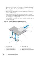
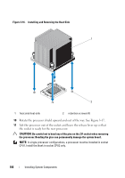
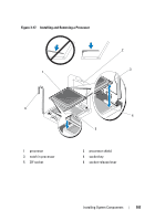
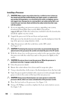
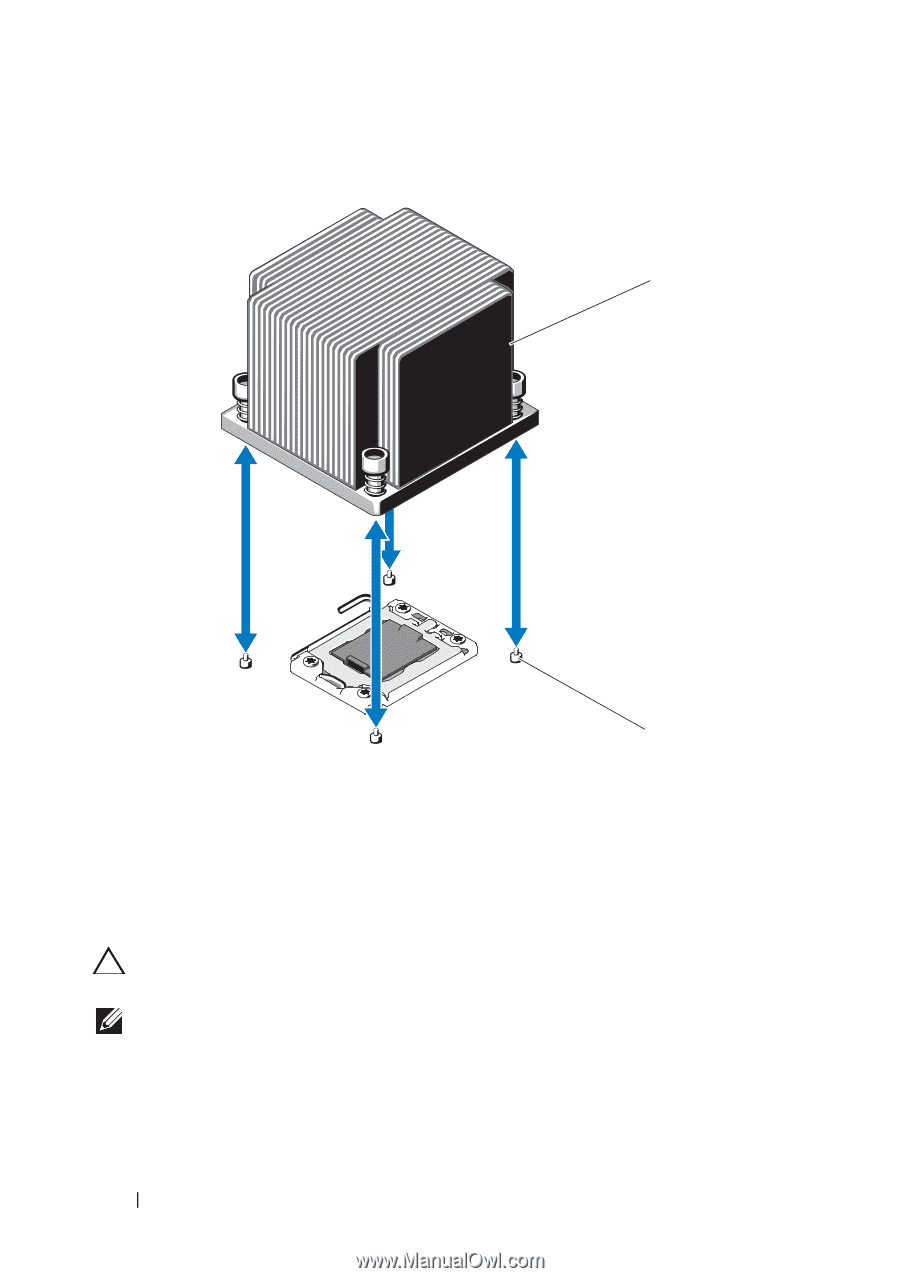
Figure 3-16. Installing and Removing the Heat Sink 1 2 1 heat sink heat-sink 2 retention screws (4) 10 Rotate the processor shield upward and out of the way. See Figure 3-17. 11 Lift the processor out of the socket and leave the release lever up so that the socket is ready for the new processor. CAUTION: Be careful not to bend any of the pins on the ZIF socket when removing the processor. Bending the pins can permanently damage the system board. NOTE: In single-processor configurations, a processor must be installed in socket CPU1. Install the blank in socket CPU2 only. 106 Installing System Components
-
 1
1 -
2
-
3
-
4
-
5
-
6
-
7
-
8
-
9
-
10
-
11
-
12
-
13
-
14
-
15
-
16
-
17
-
18
-
19
-
20
-
21
-
22
-
23
-
24
-
25
-
26
-
27
-
28
-
29
-
30
-
31
-
32
-
33
-
34
-
35
-
36
-
37
-
38
-
39
-
40
-
41
-
42
-
43
-
44
-
45
-
46
-
47
-
48
-
49
-
50
-
51
-
52
-
53
-
54
-
55
-
56
-
57
-
58
-
59
-
60
-
61
-
62
-
63
-
64
-
65
-
66
-
67
-
68
-
69
-
70
-
71
-
72
-
73
-
74
-
75
-
76
-
77
-
78
-
79
-
80
-
81
-
82
-
83
-
84
-
85
-
86
-
87
-
88
-
89
-
90
-
91
-
92
-
93
-
94
-
95
-
96
-
 97
97 -
 98
98 -
 99
99 -
 100
100 -
 101
101 -
 102
102 -
 103
103 -
 104
104 -
 105
105 -
 106
106 -
 107
107 -
108
-
109
-
110
-
111
-
112
-
113
-
114
-
115
-
116
-
117
-
118
-
119
-
120
-
121
-
122
-
123
-
124
-
125
-
126
-
127
-
128
-
129
-
130
-
131
-
132
-
133
-
134
-
135
-
136
-
137
-
138
-
139
-
140
-
141
-
142
-
143
-
144
-
145
-
146
-
147
-
148
-
149
-
150
-
151
-
152
 |
 |
106
Installing System Components
Figure 3-16.
Installing and Removing the Heat Sink
10
Rotate the processor shield upward and out of the way. See Figure 3-17.
11
Lift the processor out of the socket and leave the release lever up so that
the socket is ready for the new processor.
CAUTION:
Be careful not to bend any of the pins on the ZIF socket when removing
the processor. Bending the pins can permanently damage the system board.
NOTE:
In single-processor configurations, a processor must be installed in socket
CPU1. Install the blank in socket CPU2 only.
1
heat sink heat-sink
2
retention screws (4)
2
1