Dell Dimension 4700C Owner's Manual - Page 64
Addressing Memory With 4-GB Configurations, Installing Memory - processor upgrade
 |
View all Dell Dimension 4700C manuals
Add to My Manuals
Save this manual to your list of manuals |
Page 64 highlights
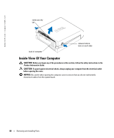
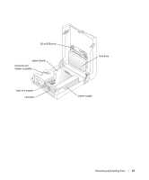
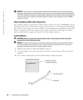
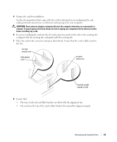
www.dell.com | support.dell.com NOTICE: If you remove your original memory modules from the computer during a memory upgrade, keep them separate from any new modules that you may have, even if you purchased the new modules from Dell. If possible, do not pair an original memory module with a new memory module. Otherwise, your computer may not start properly. You should install your original memory modules as a pair in DIMM connectors 1 and 2. Addressing Memory With 4-GB Configurations Your computer supports a maximum of 4 GB of memory when you use two 2-GB DIMMs. Current operating systems, such as Microsoft® Windows® XP, can only use a maximum of 4 GB of address space; however, the amount of memory available to the operating system is slightly less than 4 GB. Certain components within the computer require address space in the 4-GB range. Any address space reserved for these components cannot be used by computer memory. Installing Memory CAUTION: Before you begin any of the procedures in this section, follow the safety instructions located in the Product Information Guide. NOTICE: To prevent static damage to components inside your computer, discharge static electricity from your body before you touch any of your computer's electronic components. You can do so by touching an unpainted metal surface on the computer chassis. 1 Follow the procedures in "Before You Begin" on page 53. 2 Lay the computer on its side so that the system board is on the bottom of the inside of the computer. 3 Press out the securing clip at each end of the memory module connector. memory connector closest to processor securing clips (2) connector 64 Removing and Installing Parts
-
 1
1 -
2
-
3
-
4
-
5
-
6
-
7
-
8
-
9
-
10
-
11
-
12
-
13
-
14
-
15
-
16
-
17
-
18
-
19
-
20
-
21
-
22
-
23
-
24
-
25
-
26
-
27
-
28
-
29
-
30
-
31
-
32
-
33
-
34
-
35
-
36
-
37
-
38
-
39
-
40
-
41
-
42
-
43
-
44
-
45
-
46
-
47
-
48
-
49
-
50
-
51
-
52
-
53
-
54
-
55
-
56
-
57
-
58
-
 59
59 -
 60
60 -
 61
61 -
 62
62 -
 63
63 -
 64
64 -
 65
65 -
 66
66 -
 67
67 -
 68
68 -
 69
69 -
70
-
71
-
72
-
73
-
74
-
75
-
76
-
77
-
78
-
79
-
80
-
81
-
82
-
83
-
84
-
85
-
86
-
87
-
88
-
89
-
90
-
91
-
92
-
93
-
94
-
95
-
96
-
97
-
98
-
99
-
100
-
101
-
102
-
103
-
104
-
105
-
106
-
107
-
108
-
109
-
110
-
111
-
112
-
113
-
114
-
115
-
116
 |
 |
