Dell EqualLogic PS4210XV35 EqualLogic PS4210 Storage Arrays - Installation and - Page 21
Set Up a Serial Connection to the Array, AC Power Supply Switch and LEDs
 |
View all Dell EqualLogic PS4210XV35 manuals
Add to My Manuals
Save this manual to your list of manuals |
Page 21 highlights
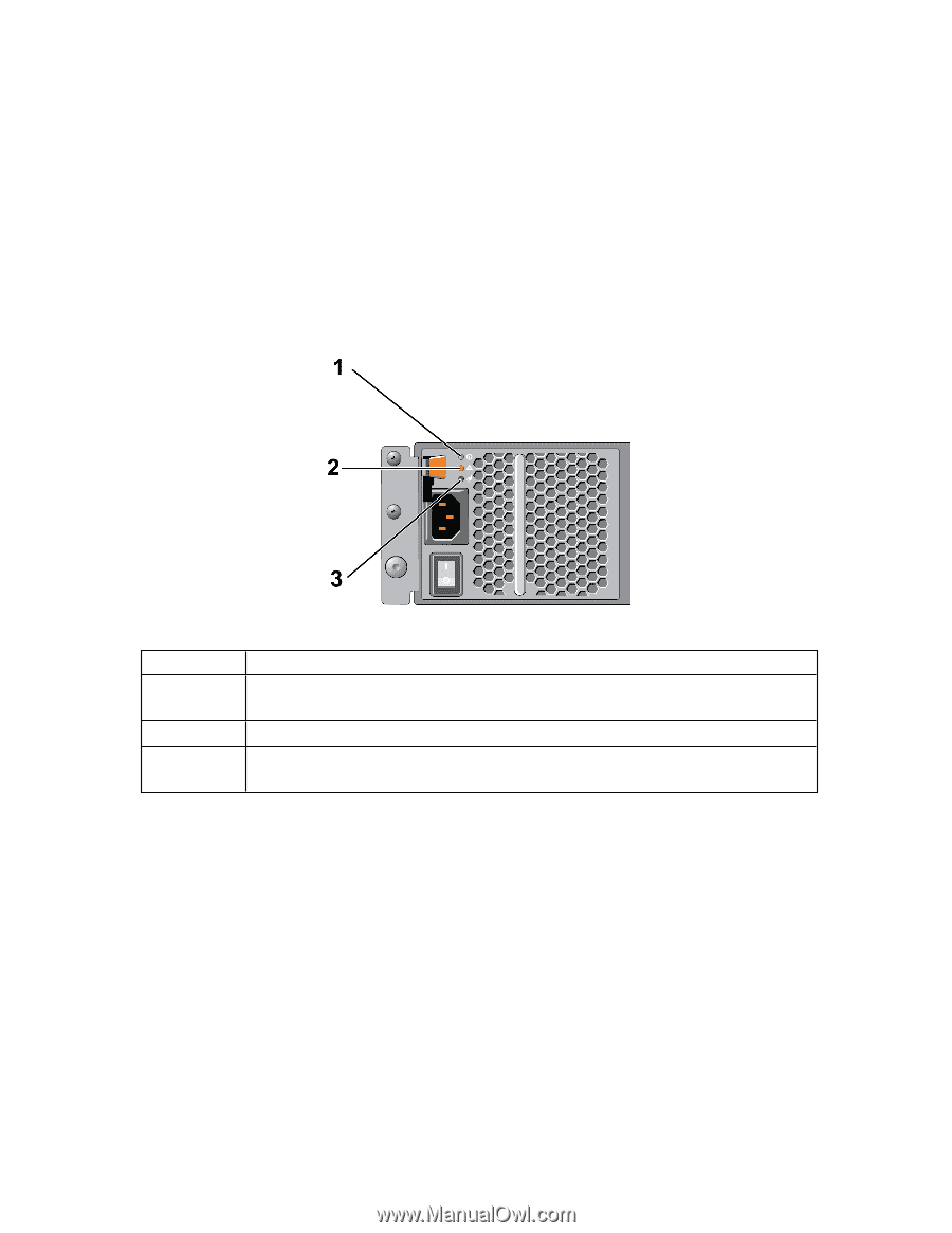
PS4210 Installation Guide 3 Connecting the Array Cables 1. Find the power switch, located either below the power plug. See Figure 8. 2. Press the power switch to the ON position. The power indicators will light. Batteries will start to charge and some hardware components will start to synchronize. LEDs will indicate these normal activities. The battery backup unit installed in each controller is shipped in a partially discharged state. The first time the system is powered on, a boot delay of up to 30 minutes might be experienced while the battery is charged to full capacity. The location of the LEDs is shown in the following illustration. Table 4 provides LED descriptions. Figure 8: AC Power Supply Switch and LEDs Callout 1 2 3 Table 4: Power Supply LED Descriptions Description Power Supply status. This LED is lit (green) when the switch is on and the power supply is providing power to the array. Error. This LED is lit (amber) if the power supply has a problem. Input Power. This LED is lit (green) as long as main power is connected to the power supply. Set Up a Serial Connection to the Array If you plan to use the setup utility to configure the software, you must set up a serial connection between the array and a computer. If you plan to use the Remote Setup wizard, you do not need a serial connection. For information about Remote Setup wizard requirements, see the Host Integration Tool for Microsoft® Installation and User's Guide or the Host Integration Tool for Linux® Installation and User's Guide. The serial cable shipped with the array is a standard null-modem cable with a female DB9 connector on each end. You might have to make or buy an adapter cable (one DB9 connector and one RJ45 connector) to connect the array to some terminal server models. See Serial Cable Pinout Information on page 15. Attach the cable to the serial port on the active control module and to a console terminal or a computer running a terminal emulator. The active control module has two green LEDS and the secondary control module has one green and one amber LED. 13
-
 1
1 -
2
-
3
-
4
-
5
-
6
-
7
-
8
-
9
-
10
-
11
-
12
-
13
-
14
-
15
-
 16
16 -
 17
17 -
 18
18 -
 19
19 -
 20
20 -
 21
21 -
 22
22 -
 23
23 -
 24
24 -
 25
25 -
 26
26 -
27
-
28
-
29
-
30
-
31
-
32
-
33
-
34
-
35
-
36
-
37
-
38
-
39
-
40
-
41
-
42
-
43
-
44
-
45
-
46
-
47
-
48
 |
 |