Dell EqualLogic PS6210X PS6210 Hardware Owners Manual - Page 21
Maintaining Control Modules, Control Module Features
 |
View all Dell EqualLogic PS6210X manuals
Add to My Manuals
Save this manual to your list of manuals |
Page 21 highlights
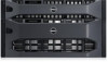
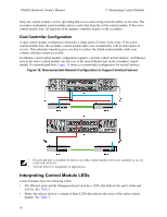
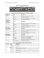
3 Maintaining Control Modules Different PS Series array models contain different control module types. The combination of chassis type, control module pair, and drives determines the PS Series array model number. The control modules in a PS Series array contain the PS Series firmware, which provides the Group Manager GUI, the command line interface, and all the array and storage management functions and features. Ideally, an array has two control modules (which must be of the same type) to avoid a single point of failure for the array. A PS6210 array includes two hot-swappable Type 15 control modules. One functioning control module is required for array operation. You access control modules from the rear of the array. Control Module Features The Type 15 control module includes: • Two pairs of Ethernet ports with two shared LEDs indicating status and activity: - One pair of 10GBASE-T ports, labeled Ethernet 0 and Ethernet 1 - One pair of SFP+ ports, labeled Ethernet 0 and Ethernet 1 Only one of two ports with the same numbered port can be used at a time. If both ports are attached to an active switch, the control module will prefer to communicate over the SFP+ interface. • One 10Mb/100Mbps port, labeled MANAGEMENT, for use only if you configure a management network. The management port has two LEDs to indicate status and activity. See Configuring the Management Port on page 29 for more information. • A column of LEDs labeled PWR (power), ERR (error condition) and ACT (activity) that indicate the status of the control module. • A recessed button labeled STANDBY ON/OFF that allows you to quickly shut down the array in certain circumstances. See About the Standby On/Off Button on page 19 for more information. • One serial port (for use if no network access to the array is available). • A field-replaceable microSD card containing the PS Series firmware. The microSD card is accessed from the rear of the control module. • A release button and latch to release the control module from the array for replacement. The release lever has a switch that detects activation and prompts the array to save data to nonvolatile storage, thereby protecting your data. Do not mix control module types in an array. Always make sure both control modules are the same type and color. See the latest PS Series Release Notes for information about other supported control modules. About Control Module Configurations While an array can run using only one control module, it is not recommended because this configuration creates a single point of failure. If the control module fails and no other module can take over, all access to your volumes stops until the failure is repaired or the control module is replaced. 15
-
 1
1 -
2
-
3
-
4
-
5
-
6
-
7
-
8
-
9
-
10
-
11
-
12
-
13
-
14
-
15
-
 16
16 -
 17
17 -
 18
18 -
 19
19 -
 20
20 -
 21
21 -
 22
22 -
 23
23 -
 24
24 -
 25
25 -
 26
26 -
27
-
28
-
29
-
30
-
31
-
32
-
33
-
34
-
35
-
36
-
37
-
38
-
39
-
40
-
41
-
42
-
43
-
44
-
45
-
46
-
47
-
48
 |
 |
