Dell Force10 S25-01-GE-24V Quick Start Guide for the S25 System - Page 13
cord are available, based on country requirements., AC power outlets
 |
View all Dell Force10 S25-01-GE-24V manuals
Add to My Manuals
Save this manual to your list of manuals |
Page 13 highlights
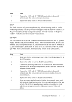
Step Task 3 Connect the -48 V and -48 V RTN (Return) cables to the switch terminals and then to the remote power sources. 4 Replace the safety covers on the DC terminal block. S25P The S25P has two AC power supplies acting in load-sharing mode or can be used independently. Use the power cords shipped with the S25P to connect it to AC power outlets, ideally on separate circuits. Several versions of the power cord are available, based on country requirements. S25P-DC The PSU side of the S25P-DC contains two terminal blocks for two DC power supply inputs acting in load-sharing mode. The left terminal block, as you face the PSU side, corresponds to the DC2 status LED on the I/O side of the switch; DC1 is on the right. Cables must be sized for 11.5 A service at -48VDC input (per NEC in the United States. Internationally, follow local safety codes.) Step Task 1 Make sure that the remote power source (the circuit breaker panel) is in the OFF position. 2 Remove the safety cover from the DC terminal block. 3 Connect the grounding cable to the FG terminal first, then connect the opposite end to the appropriate grounding point at your site to ensure an adequate chassis ground. 4 Connect the -48 V and -48 V RTN (Return) cables to the switch terminals and then to the remote power sources, ideally on separate circuit breakers. 5 Replace the safety covers on the DC terminal blocks. 6 If you are connecting both terminal blocks, do not supply power until both terminal blocks are connected. You can supply power to either one or both. The S25P-DC uses the power supplies in load-sharing mode and does not set a precedence for either power source. Failover is hitless. Installing the Hardware 11
-
 1
1 -
2
-
3
-
4
-
5
-
6
-
7
-
 8
8 -
 9
9 -
 10
10 -
 11
11 -
 12
12 -
 13
13 -
 14
14 -
 15
15 -
 16
16 -
 17
17 -
 18
18 -
19
-
20
-
21
-
22
-
23
-
24
-
25
-
26
 |
 |