Dell Force10 S50-01-GE-48T Installing S50N and S50V Systems - Page 5
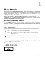
About this Guide, Information Symbols and Warnings
 |
View all Dell Force10 S50-01-GE-48T manuals
Add to My Manuals
Save this manual to your list of manuals |
Page 5 highlights
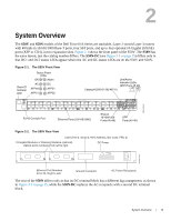
1 About this Guide This guide provides site preparation recommendations, step-by-step procedures for rack mounting and desk mounting the S50V or S50N switches (and related models, such as S50N-DC), inserting optional modules, and connecting to a power source. Except where noted, descriptions and instructions in this guide apply to all variants of these switches. After you have completed the hardware installation and power-up of the switch, refer to the SFTOS™ Configuration Guide for software configuration information and to the SFTOS™ Command Reference for detailed Command Line Interface (CLI) information. Information Symbols and Warnings The following graphic symbols are used in this document to bring attention to hazards that exist when handling the switch and its components. Please read these alerts and heed their warnings and cautions. Table 1-1 describes symbols contained in this guide. Table 1-1. Information Symbols Symbol Warning Description Note This symbol informs you of important operational information. Caution This symbol informs you that improper handling and installation could result in equipment damage or loss of data. Warning This symbol signals information about hardware handling that could result in injury. WARNING: The installation of this equipment shall be performed by trained and qualified personnel only. Read this guide before installing and powering up this equipment. This equipment contains two power cords. Disconnect both power cords before servicing. WARNING: Class 1 laser product. Attention: Produit laser de classe 1 Warnung: Laserprodukt der Klasse 1 About this Guide | 5
-
 1
1 -
 2
2 -
 3
3 -
 4
4 -
 5
5 -
 6
6 -
 7
7 -
 8
8 -
 9
9 -
 10
10 -
 11
11 -
12
-
13
-
14
-
15
-
16
-
17
-
18
-
19
-
20
-
21
-
22
-
23
-
24
-
25
-
26
-
27
-
28
-
29
-
30
-
31
-
32
-
33
-
34
-
35
-
36
-
37
-
38
-
39
-
40
-
41
-
42
-
43
-
44
-
45
-
46
-
47
-
48
-
49
-
50
-
51
-
52
-
53
-
54
-
55
-
56
-
57
-
58
-
59
-
60
-
61
-
62
-
63
-
64
 |
 |
