Dell Force10 S50-01-GE-48T Quick Start Guide for the S50N and S50V Systems - Page 10
Power Up Sequence, Supply Power and Power Up the System
 |
View all Dell Force10 S50-01-GE-48T manuals
Add to My Manuals
Save this manual to your list of manuals |
Page 10 highlights
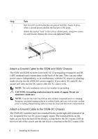
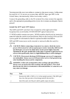
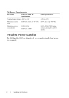
CAUTION: You can insert and connect XFP transceivers while the switch is operating. You can also disconnect and remove XFP transceivers while the switch is operating. However, inserting or removing the module is not supported; it can crash or lock up the switch, requiring a reboot. CAUTION: The CX4 module does not use transceivers. However, you can use a CX4 cable with an XFP port by inserting a CX4 XFP converter (catalog name GP- XFP-1CX4) into the slot. An XFP port does not support the use of the cx4-cable-length command. NOTE: For details on Dell Force10 supported optics, refer to http://www.force10networks.com/products/specifications.asp Power Up Sequence Supply Power and Power Up the System There is no power switch. Connecting the switch to either an AC or DC power source starts the switch. The S50V and S50N switches have both AC (3-prong plug receptacle) and DC (-48V terminal-type) connections on the back of the unit. They can use either power source independently or in combination, with the DC source in a backup mode (except for the 470W DC power supply). You have three options for providing power to the switch - AC only, DC only, or using both AC and DC sources. If you select the third choice - AC and DC - the switch will only use the DC source after the AC source fails. The rear of the S50N and S50V models have both an auto-sensing 110/220V AC receptacle and a standard -48V terminal-type DC connector. The rear of an S50N differs only in the arrangement of the lugs on its DC terminal block. Each system ships only with the AC power cord. Dell Force10 recommends re-inspecting your system prior to powering up. Verify that: • The equipment is properly secured to the rack and properly grounded. • The equipment rack is properly mounted and grounded. • The ambient temperature around the unit (which may be higher than the room temperature) is within the limits specified for the unit. • There is sufficient airflow around the unit. • The input circuits are correctly sized for the loads and that sufficient overcurrent protection devices are used. 8 Installing the Hardware
-
 1
1 -
2
-
3
-
4
-
 5
5 -
 6
6 -
 7
7 -
 8
8 -
 9
9 -
 10
10 -
 11
11 -
 12
12 -
 13
13 -
 14
14 -
 15
15 -
16
-
17
-
18
-
19
-
20
-
21
-
22
-
23
-
24
 |
 |