Dell Inspiron 16 Plus 7620 Service Manual - NVIDIA GeForce RTX 3060 - Page 50
Power-adapter port, Removing the power-adapter port
 |
View all Dell Inspiron 16 Plus 7620 manuals
Add to My Manuals
Save this manual to your list of manuals |
Page 50 highlights
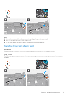
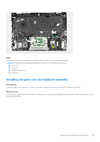
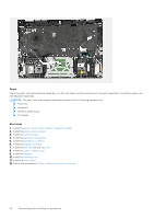
10. Place the Type-C port-bracket on the system board. 11. Replace the two screws (M2x5) that secure the Type-C port-bracket to the system board. 12. Connect the keyboard cable to the system board and close the latch. 13. Connect the keyboard-backlight cable to system board and close the latch. 14. Connect the speaker (woofer) cable to the system board. 15. Adhere the Mylar back on the speaker (woofer) cable. 16. Connect the touchpad cable to system board and close the latch. 17. Connect the power-button board cable to the system board and close the latch. Next steps 1. Install the right fan. 2. Install the left fan. 3. Install the heat sink. 4. Install the wireless card. 5. Install the M.2 2230 solid-state drive or M.2 2280 solid-state drive, whichever applicable. 6. Install the memory module. 7. Install the base cover. 8. Follow the procedure in After working inside your computer. Power-adapter port Removing the power-adapter port Prerequisites 1. Follow the procedure in Before working inside your computer. NOTE: Ensure that your computer is in Service Mode. For more information see, step 6 in Before working inside your computer. 2. Remove the base cover. 3. Remove the system board. About this task NOTE: For this configuration where the computer is offered with GeForce RTX 3060, the system board can be removed with the solid-state drive, memory module, and heat sink attached. The following image(s) indicate the location of the power-adapter port and provides a visual representation of the removal procedure. 50 Removing and installing components
-
 1
1 -
2
-
3
-
4
-
5
-
6
-
7
-
8
-
9
-
10
-
11
-
12
-
13
-
14
-
15
-
16
-
17
-
18
-
19
-
20
-
21
-
22
-
23
-
24
-
25
-
26
-
27
-
28
-
29
-
30
-
31
-
32
-
33
-
34
-
35
-
36
-
37
-
38
-
39
-
40
-
41
-
42
-
43
-
44
-
 45
45 -
 46
46 -
 47
47 -
 48
48 -
 49
49 -
 50
50 -
 51
51 -
 52
52 -
 53
53 -
 54
54 -
 55
55 -
56
-
57
-
58
-
59
-
60
-
61
-
62
-
63
-
64
-
65
-
66
-
67
-
68
-
69
 |
 |
