Dell Inspiron 17 5765 Inspiron 17 5000 Service Manual - Page 63
Replacing the optical-drive interposer, Procedure, Post-requisites
 |
View all Dell Inspiron 17 5765 manuals
Add to My Manuals
Save this manual to your list of manuals |
Page 63 highlights
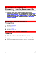
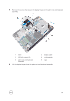
GUID-7D3D6B04-3ECE-4E21-8CF6-A1AFBDE2E206 Replacing the optical-drive interposer WARNING: Before working inside your computer, read the safety information that shipped with your computer and follow the steps in Before working inside your computer. After working inside your computer, follow the instructions in After working inside your computer. For more safety best practices, see the Regulatory Compliance home page at www.dell.com/ regulatory_compliance. GUID-6F12CA2E-213B-4753-A062-2A82638E7B84 Procedure 1 Align the screw holes on the optical-drive connector board with the screw holes on the palm rest and keyboard assembly. 2 Replace the screws that secure the optical-drive connector board to the palm rest and keyboard assembly. 3 Press down on the latch to connect the optical-drive connector board cable to the optical-drive connector board. GUID-F1EB99CE-84AE-4B01-9EB3-3F00C9B856FB Post-requisites 1 Replace the battery. 2 Replace the base cover. 3 Replace the optical drive. 63
-
 1
1 -
2
-
3
-
4
-
5
-
6
-
7
-
8
-
9
-
10
-
11
-
12
-
13
-
14
-
15
-
16
-
17
-
18
-
19
-
20
-
21
-
22
-
23
-
24
-
25
-
26
-
27
-
28
-
29
-
30
-
31
-
32
-
33
-
34
-
35
-
36
-
37
-
38
-
39
-
40
-
41
-
42
-
43
-
44
-
45
-
46
-
47
-
48
-
49
-
50
-
51
-
52
-
53
-
54
-
55
-
56
-
57
-
 58
58 -
 59
59 -
 60
60 -
 61
61 -
 62
62 -
 63
63 -
 64
64 -
 65
65 -
 66
66 -
 67
67 -
 68
68 -
69
-
70
-
71
-
72
-
73
-
74
-
75
-
76
-
77
-
78
-
79
-
80
-
81
-
82
-
83
-
84
-
85
-
86
-
87
-
88
-
89
-
90
-
91
-
92
-
93
-
94
-
95
-
96
-
97
-
98
-
99
-
100
-
101
-
102
-
103
-
104
-
105
-
106
-
107
-
108
-
109
-
110
-
111
-
112
-
113
-
114
 |
 |
