Dell Inspiron 17 5765 Inspiron 17 5000 Service Manual - Page 77
Removing the heat-sink assembly, Prerequisites, Procedure
 |
View all Dell Inspiron 17 5765 manuals
Add to My Manuals
Save this manual to your list of manuals |
Page 77 highlights
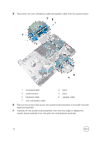
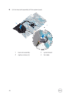
GUID-A4C65F77-E1D1-4595-B52B-D281E90F786D Removing the heat-sink assembly WARNING: Before working inside your computer, read the safety information that shipped with your computer and follow the steps in Before working inside your computer. After working inside your computer, follow the instructions in After working inside your computer. For more safety best practices, see the Regulatory Compliance home page at www.dell.com/ regulatory_compliance. WARNING: The heat sink may become hot during normal operation. Allow sufficient time for the heat sink to cool before you touch it. CAUTION: For maximum cooling of the processor, do not touch the heat transfer areas on the heat sink. The oils in your skin can reduce the heat transfer capability of the thermal grease. GUID-EA7A305F-3190-4783-BABE-83A2280E01FF Prerequisites 1 Remove the optical drive. 2 Remove the base cover. 3 Remove the battery. 4 Remove the system-board assembly. GUID-11B426F1-C9E3-47E8-A675-E0C9AD7371C1 Procedure NOTE: Place the system board on a clean and flat surface. 1 Disconnect the fan cable from the system board. 2 In sequential order, as indicated on the heat-sink assembly, loosen the captive screws that secure the heat-sink assembly to the system board. 3 Remove the screw that secures the heat-sink assembly to the system board. 77
-
 1
1 -
2
-
3
-
4
-
5
-
6
-
7
-
8
-
9
-
10
-
11
-
12
-
13
-
14
-
15
-
16
-
17
-
18
-
19
-
20
-
21
-
22
-
23
-
24
-
25
-
26
-
27
-
28
-
29
-
30
-
31
-
32
-
33
-
34
-
35
-
36
-
37
-
38
-
39
-
40
-
41
-
42
-
43
-
44
-
45
-
46
-
47
-
48
-
49
-
50
-
51
-
52
-
53
-
54
-
55
-
56
-
57
-
58
-
59
-
60
-
61
-
62
-
63
-
64
-
65
-
66
-
67
-
68
-
69
-
70
-
71
-
 72
72 -
 73
73 -
 74
74 -
 75
75 -
 76
76 -
 77
77 -
 78
78 -
 79
79 -
 80
80 -
 81
81 -
 82
82 -
83
-
84
-
85
-
86
-
87
-
88
-
89
-
90
-
91
-
92
-
93
-
94
-
95
-
96
-
97
-
98
-
99
-
100
-
101
-
102
-
103
-
104
-
105
-
106
-
107
-
108
-
109
-
110
-
111
-
112
-
113
-
114
 |
 |
