Dell Inspiron 17 7746 Service Manual - Page 51
Remove the screws that secure the display hinges to the palm-rest assembly.
 |
View all Dell Inspiron 17 7746 manuals
Add to My Manuals
Save this manual to your list of manuals |
Page 51 highlights
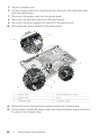
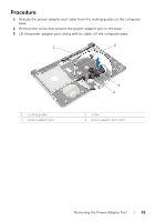
3 Place the computer on the edge of the table with the palm rest on the table so that the display assembly extends past the table edge with the display hinges facing up. 4 Remove the screws that secure the display hinges to the palm-rest assembly. 1 2 3 4 1 palm-rest assembly 3 display hinges (2) 2 screws (4) 4 display assembly Removing the Display Assembly | 51
-
 1
1 -
2
-
3
-
4
-
5
-
6
-
7
-
8
-
9
-
10
-
11
-
12
-
13
-
14
-
15
-
16
-
17
-
18
-
19
-
20
-
21
-
22
-
23
-
24
-
25
-
26
-
27
-
28
-
29
-
30
-
31
-
32
-
33
-
34
-
35
-
36
-
37
-
38
-
39
-
40
-
41
-
42
-
43
-
44
-
45
-
 46
46 -
 47
47 -
 48
48 -
 49
49 -
 50
50 -
 51
51 -
 52
52 -
 53
53 -
 54
54 -
 55
55 -
 56
56 -
57
-
58
-
59
-
60
-
61
 |
 |

Removing the Display Assembly
|
51
3
Place the computer on the edge of the table with the palm rest on the table so that
the display assembly extends past the table edge with the display hinges facing up.
4
Remove the screws that secure the display hinges to the palm-rest assembly.
1
palm-rest assembly
2
screws (4)
3
display hinges (2)
4
display assembly
4
3
2
1