Dell Inspiron 20 3048 Owners Manual - Page 81
Replacing the Camera, Procedure
 |
View all Dell Inspiron 20 3048 manuals
Add to My Manuals
Save this manual to your list of manuals |
Page 81 highlights
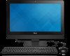
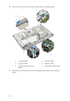
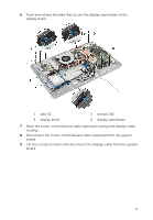
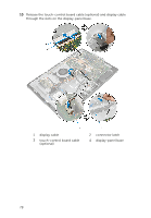
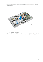
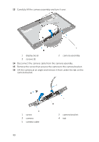
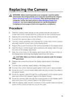
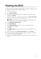
Replacing the Camera WARNING: Before working inside your computer, read the safety information that shipped with your computer and follow the steps in Before Working Inside Your Computer. After working inside your computer, follow the instructions in After Working Inside Your Computer. For more safety best practices, see the Regulatory Compliance home page at dell.com/regulatory_compliance. Procedure 1 Slide the camera under the tab on the camera bracket and align the screw hole on the camera with the screw hole on the camera bracket. 2 Replace the screw that secures the camera to the camera bracket. 3 Connect the camera cable to the camera. 4 Turn the camera assembly over and align the screw holes on the camera assembly with the screw holes on the display bezel. 5 Replace the screws that secure the camera assembly to the display bezel. 6 Slide the touch-control board cable (optional) and display cable through the slots on the display-panel base. 7 Align the screw holes on the display-panel base with the screw holes on the display bezel and snap the display-panel base into place. CAUTION: Make sure that no cables are placed under the displaypanel base. 8 Replace the screws that secure the display-panel base to the display bezel. 9 Connect the converter-board cable to the display panel. 10 Connect the control-buttons board cable to the control-buttons board. 11 Route the touch-control board cable (optional) and connect the cable to the system board. 12 Route the speaker cable through the routing guides on the display-panel base and connect the speaker cable to the system board. 13 Route the camera cable through the routing guides on the display-panel base and connect the camera cable to the system board. 14 Slide the display cable into the connector on the system board and press down on the connector latch to secure the cable. 81
-
 1
1 -
2
-
3
-
4
-
5
-
6
-
7
-
8
-
9
-
10
-
11
-
12
-
13
-
14
-
15
-
16
-
17
-
18
-
19
-
20
-
21
-
22
-
23
-
24
-
25
-
26
-
27
-
28
-
29
-
30
-
31
-
32
-
33
-
34
-
35
-
36
-
37
-
38
-
39
-
40
-
41
-
42
-
43
-
44
-
45
-
46
-
47
-
48
-
49
-
50
-
51
-
52
-
53
-
54
-
55
-
56
-
57
-
58
-
59
-
60
-
61
-
62
-
63
-
64
-
65
-
66
-
67
-
68
-
69
-
70
-
71
-
72
-
73
-
74
-
75
-
 76
76 -
 77
77 -
 78
78 -
 79
79 -
 80
80 -
 81
81 -
 82
82 -
 83
83 -
 84
84 -
 85
85
 |
 |