Dell Inspiron 20 3048 Owners Manual - Page 74
Replacing the System Board, Procedure, Post-requisites
 |
View all Dell Inspiron 20 manuals
Add to My Manuals
Save this manual to your list of manuals |
Page 74 highlights
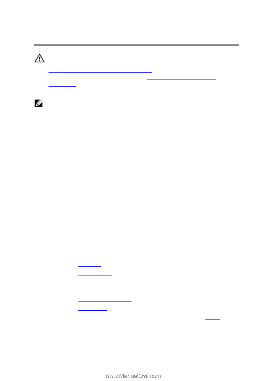
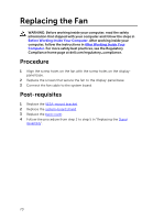
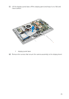
Replacing the System Board WARNING: Before working inside your computer, read the safety information that shipped with your computer and follow the steps in Before Working Inside Your Computer. After working inside your computer, follow the instructions in After Working Inside Your Computer. For more safety best practices, see the Regulatory Compliance home page at dell.com/regulatory_compliance. NOTE: Your computer's Service Tag is stored in the system board. You must enter the Service Tag in the system setup after you replace the system board. Procedure 1 Slide the ports on the system board into the slots on the display-panel base and align the screw holes on the system board with the screw holes on the display-panel base. 2 Replace the screws that secure the system board to the display-panel base. 3 Connect the fan cable, power-adapter port cable, converter-board cable, hard-drive and optical-drive power cable, optical-drive cable, hard-drive cable, control-buttons board cable, touch-control board cable (optional), speaker cable, and camera cable to the system board. For more information, see System Board Components. 4 Slide the display cable into the system-board connector and press down on the connector latch to secure the cable. Post-requisites 1 Replace the heat sink. 2 Replace the wireless card. 3 Replace the memory module(s). 4 Replace the VESA-mount bracket. 5 Replace the system-board shield. 6 Replace the back cover. 7 Follow the procedure from step 3 to step 5 in "Replacing the Stand Assembly". 74
-
 1
1 -
2
-
3
-
4
-
5
-
6
-
7
-
8
-
9
-
10
-
11
-
12
-
13
-
14
-
15
-
16
-
17
-
18
-
19
-
20
-
21
-
22
-
23
-
24
-
25
-
26
-
27
-
28
-
29
-
30
-
31
-
32
-
33
-
34
-
35
-
36
-
37
-
38
-
39
-
40
-
41
-
42
-
43
-
44
-
45
-
46
-
47
-
48
-
49
-
50
-
51
-
52
-
53
-
54
-
55
-
56
-
57
-
58
-
59
-
60
-
61
-
62
-
63
-
64
-
65
-
66
-
67
-
68
-
 69
69 -
 70
70 -
 71
71 -
 72
72 -
 73
73 -
 74
74 -
 75
75 -
 76
76 -
 77
77 -
 78
78 -
 79
79 -
80
-
81
-
82
-
83
-
84
-
85
 |
 |