Dell Inspiron 3455 AIO Inspiron 24 3455 Service Manual - Page 67
Replacing the control-buttons board, Procedure, Post-requisites
 |
View all Dell Inspiron 3455 AIO manuals
Add to My Manuals
Save this manual to your list of manuals |
Page 67 highlights
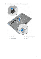
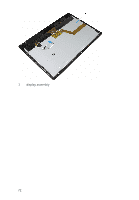
Replacing the control-buttons board WARNING: Before working inside your computer, read the safety information that shipped with your computer and follow the steps in Before working inside your computer. After working inside your computer, follow the instructions in After working inside your computer. For more safety best practices, see the Regulatory Compliance home page at dell.com/regulatory_compliance. Procedure 1 Slide the control-buttons board cable into the connector on the controlbuttons board and press down on the latch to secure the cable. 2 Replace the control-buttons board into the slot on the display bezel. 3 Route the control-buttons board cable through the routing guides and adhere the control-buttons board cable to the display-assembly base. 4 Slide the control-buttons board cable into the connector on the systems board and press down on the latch to secure the cable. Post-requisites 1 Replace the VESA-mount bracket. 2 Replace the back cover. 3 Replace the stand assembly. 67
-
 1
1 -
2
-
3
-
4
-
5
-
6
-
7
-
8
-
9
-
10
-
11
-
12
-
13
-
14
-
15
-
16
-
17
-
18
-
19
-
20
-
21
-
22
-
23
-
24
-
25
-
26
-
27
-
28
-
29
-
30
-
31
-
32
-
33
-
34
-
35
-
36
-
37
-
38
-
39
-
40
-
41
-
42
-
43
-
44
-
45
-
46
-
47
-
48
-
49
-
50
-
51
-
52
-
53
-
54
-
55
-
56
-
57
-
58
-
59
-
60
-
61
-
 62
62 -
 63
63 -
 64
64 -
 65
65 -
 66
66 -
 67
67 -
 68
68 -
 69
69 -
 70
70 -
 71
71 -
 72
72 -
73
-
74
-
75
-
76
-
77
-
78
-
79
 |
 |
